background image

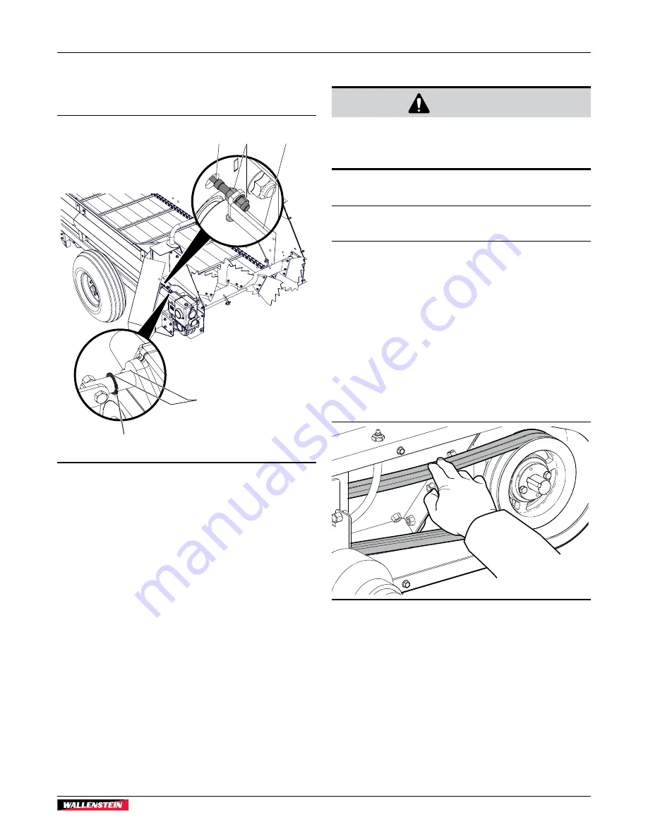
8.7.3  Adjust the Shift Cable

If the gearbox is not shifting gears correctly, the shift cable may 
require adjustment.

01464

2

1

5

4

3

Fig.  22 – 

Shift-cable Adjustment

1. 

Set the machine to a safe condition. For instructions, see 

Safe Condition on page 9

2. 

Use the speed-control rope to set the beater and apron 
drive speed to 1 (low). For more information, see 

Controls 

on page 20

.

3. 

Open the left-hand side, rear shield door.'

4. 

Locate the shift cable (1) that is attached to the gearbox 
shift rod (3).

5. 

Loosen the two lock nuts (2) that are on the end of the shift 
cable.

6. 

Adjust the position of the shift cable until the shift rod 
retaining ring (5) is approximately 1 1/16 in (27 mm) (4) 
from the gearbox housing.

7. 

Tighten the two lock nuts to secure the shift cable to the 
shift rod.

8.8  Drive Belt 

 WARNING!

Machine shown with shields removed for 

illustrative purposes only. Never operate 

machine with shields removed.

W001

8.8.1  Adjust the Drive Belt Tension

IMPORTANT!  Drive belt deflection should not measure 
more than 3/4–1 in. (20–25 mm).

Drive belts transmit PTO power to the drive shaft. The drive 
shaft then provides power to the gearbox that drives the beater 
bar and apron-chain assembly.

When a belt is in disrepair or loose, the ability to efficiently 
transfer power from the PTO to the drive shaft may be affected. 
It is important to check the condition and tension of the belts on 
a regular basis. Replace a frayed, cracked, or worn drive belt. 

Remove the belt-drive shield to check the belt tension. Use a 
drive belt tension gauge for accurate measurement. If a gauge 
is not available, push on the belts with your fingers to observe 
their deflection.

01399

Fig.  23 – 

Drive Belt Deflection

MX130P
Manure Spreader

Service and Maintenance

33

Summary of Contents for MX130P

Page 1: ...OPERATOR S MANUAL Manure Spreader MX130P Document Number Z97104_En Rev Apr 2021 ...

Page 2: ...ce and to provide to new operators or owners Call your Wallenstein dealer or the Distributor if you need assistance information or additional copies of the manual Units of measurement in Wallenstein Equipment technical manuals are written as US Customary SI metric WARNING Do not attempt to start or operate the machine without thoroughly reviewing this manual for safe and proper operation Always ke...

Page 3: ...Sizing a PTO Shaft 18 5 2 Installing a PTO Shaft 19 6 Controls 20 7 Operating Instructions 21 7 1 Operating Safety 21 7 2 Stopping 22 7 3 Stopping in an Emergency 22 7 4 Pre operation Checks 22 7 5 Machine Break In 22 7 6 Loading 23 7 7 Spreading 24 7 8 Cleaning Out 24 7 9 Removing a Jam 24 7 10 Transporting 25 7 11 Storage 26 8 Service and Maintenance 27 8 1 Maintenance Safety 27 8 2 Grease Type ...

Page 4: ...ty State Province ZIP Postal Code Phone Number Dealer Inspection Checklist All belts are aligned and the tension is correct Drive chain tension is correct PTO shaft telescopes and shield turns Clutch is adjusted and functions correctly Gearbox oil level is correct Apron chain moves freely and the tension is correct Beater bar moves freely Speed control mechanism moves freely All fasteners are tigh...

Page 5: ...TES LES NORMES QUI LUI SONT APPLICABLES EN VERTU DU REGLEMENT SUR LA SECURITE DES VEHICLES AUTOMOBILES DU CANADA EN VIGUEUR A LA DATE DE SA FABRICATION 01450 1 3 Serial Number Location Always provide the model and serial number of your Wallenstein product when ordering parts or requesting service or other information The product information plate location is shown in the following illustration Rec...

Page 6: ...al provides additional information for the operator or explains the operation of a control Product Decals provide the machine model and serial number and other important information VIN NLV MODEL Manufactured by Wallenstein Equipment Inc 7201 Line 86 Wallenstein ON N0B2S0 Canada TYPE OF VEHICLE TYPE DE VEHICLE TRA REM GAWR PNBE KG GVWR PNBV KG DIMENSION RIM JANTE E R I T PNEU COLD INFL PRESS PRESS...

Page 7: ...es CAUTION Indicates a potentially hazardous situation that if not avoided may result in minor or moderate injury It may also be used to alert against unsafe practices IMPORTANT To avoid confusing equipment protection with personal safety messages the signal word IMPORTANT indicates a situation that if not avoided could result in damage to the machine 2 3 Why SAFETY is important Accidents disable ...

Page 8: ... basis may cause permanent total hearing loss Keep a first aid kit available for use should the need arise and know how to use it Keep a fire extinguisher available for use should the need arise and know how to use it Do not use a tractor unless it is equipped with a roll over protective structure ROPS Always wear the seat belt when operating a tractor Serious injury or even death could result fro...

Page 9: ...t It is the operator s responsibility to read understand and follow ALL safety and operating instructions in this manual Train all new personnel and review instructions frequently with existing personnel Make sure that only a properly trained and physically able person uses the machine A person who has not read and understood all instructions is not qualified to use the machine An untrained operat...

Page 10: ...rators should review these topics at the start of each season The following sign off form can be used to document the required training The design and manufacture of this product conforms to the applicable provisions in the following standards ASABE S318 Safety for Agricultural Field Equipment ISO 3600 Tractors machinery for agriculture and forestry powered lawn and garden equipment Operator s man...

Page 11: ...ows the message how to avoid the hazard Hazard How to avoid the hazard Practicing good safety means becoming familiar with safety signs decals and warnings and being aware of situations that require alertness Think SAFETY Work SAFELY 1 1 3 2 4 5 1 1 3 2 4 5 01451 1 2 3 3 4 Fig 2 Safety sign Locations right hand side view Safety MX130P Manure Spreader Safety 11 ...

Page 12: ...t in beater bar paddles Keep hands loose clothing and long hair away from the beater bar paddles while they are operating 2 WARNING Risk of injury from flying debris Stay clear of manure discharge The beater bar can expel manure or other material fast enough to cause injury Safety MX130P Manure Spreader Safety 12 ...

Page 13: ...t rotation can result in machine damage 6 WARNING Risk of entanglement in rotating drive line Stay clear of the PTO shaft when the machine is operating Do not operate the machine with the PTO shaft cover removed Keep hands loose clothing and long hair away from the drive line while it is rotating 7 CAUTION Read the operator s manual Read ALL operating instructions in the manual and learn the meani...

Page 14: ... The installation area must be clean and dry The application surface must be clean and free of grease or oil The ambient temperature must be above 50 F 10 C A squeegee plastic bank card or similar tool is required to smooth out the decal Procedure NOTE Determine the exact position for the decal before removing the backing paper If possible align the decal with an edge on the machine 1 Peel the dec...

Page 15: ...wner or operator to read this manual and to train all other operators before they start working with the machine Follow all safety instructions exactly Safety is everyone s business Following the recommended procedures provides a safe working environment for the operator bystanders and the area around the work site Untrained operators are not qualified to use the machine 3 2 Operator Orientation I...

Page 16: ...he heavy duty beater bar includes ten replaceable paddles Fig 5 Manure Spreader Components 1 PTO shaft 2 Speed control indicator 3 Speed control rope guide hole rope not shown 4 Main box 130 bushel capacity 5 Apron chain assembly 6 Floorboards eight 7 Beater bar assembly 8 Beater bar and apron drive rear shield door 1 of 2 9 Side shaft shield 10 12 ply 12PR farm specialist tires 11 Main box frame ...

Page 17: ...ure that there is enough space and clearance to safely back up to the tractor 3 Use the trailer jack to raise the clevis hitch to the height of the tractor draw bar 4 Slowly back up the tractor until the draw bar and clevis hitch are aligned 5 Attach the clevis hitch Place the hitch pin through the clevis and draw bar and then install the snap lock pin to secure the hitch pin 6 Use the crank to ra...

Page 18: ...t Call this measurement B L 2 50 mm B 00944 L Fig 8 Measurement B 4 If the collapsed length A from Step 2 is longer than measurement B from Step 3 the PTO shaft must be shortened 5 Subtract B from the uncut PTO shaft measurement A A B The result is the length that BOTH halves of the PTO shaft should be shortened Call this cut length C A B C 00945 A B L 2 inches L 50 mm Fig 9 C Cut Length 6 Pull th...

Page 19: ...g pin button and push the shaft end onto the input PTO b Connect the safety chain to the implement so that the shielding does not turn during operation 2 Slide out the end of the PTO shaft up to the tractor output PTO aligning the two shaft splines 3 Press the locking pin button and push the shaft end onto the tractor output PTO 4 Once it is started slide the shaft all the way on You might hear a ...

Page 20: ...to the drive gearbox The beater bar and apron drive speed are controlled by the tractor driver using the nylon speed control rope The driver pulls and releases the speed control rope to select one of the five speed control settings 01457 Fig 12 Beater bar and Apron Drive Speed Control The five position speed control indicator is located on the front of the main box near the PTO connection 01458 5 ...

Page 21: ... can cause injury or death Do not allow anyone within 20 ft 6 m of the manure spreader during operation Objects thrown from the rear of the manure spreader could cause injury Always remove loose manure or soil from tires and other parts of the equipment before entering a roadway Manure or wet soil left on the roadway by your tractor and manure spreader can cause slippery road conditions for other ...

Page 22: ...hat they are secure Check the tightness of all fasteners Make sure that your equipment is working and in good repair Make sure that the operator is wearing the appropriate PPE such as a hard hat safety eyewear safety footwear safety vest hearing protection and gloves Make sure that the operator is not wearing loose fitting clothing or jewelry and that long hair is tied back 7 5 Machine Break In Al...

Page 23: ...ack This loading method spreads the manure uniformly in the main box Do not overload the manure spreader Break up any large chunks of manure Be cautious of foreign objects in the manure that could jam the beater bar and paddles and potentially damage the machine Smaller objects could be thrown toward the driver If you are loading the manure spreader in freezing weather be aware of frozen chunks of...

Page 24: ...quipment com 7 8 Cleaning Out WARNING Moving parts are exposed and an entanglement hazard is present Make sure that the engine is turned off and the PTO is disengaged when working in or around the manure spreader IMPORTANT Do not use a pressure washer on sealed bearings Dirt can be forced inside the bearing case and cause the bearing to eventually fail 1 Stop the tractor turn off the engine and se...

Page 25: ...does not include the required lights reflectors and markings Before taking the manure spreader on a public roadway install the required lighting reflectors and markings and make sure that they are in good working condition For specific requirements contact your local transportation authority 7 10 1Transport Safety Never allow riders on the manure spreader Do not exceed a safe travel speed Slow dow...

Page 26: ...o not store the manure spreader with wet manure in it or store it outdoors when it is loaded Failure to do this can cause the metal parts to corrode 1 Park the manure spreader in a flat dry location 2 Lower the trailer jack and then lock it in position 3 Rest the PTO shaft on the PTO holder 4 Chock the wheels to prevent movement 5 During freezing temperatures remove excess moisture from the moving...

Page 27: ...e dealer or repair service complete all required tire maintenance Do not attempt to mount a tire unless you have the proper equipment and experience for this task Failure to follow the correct procedures when mounting a tire on a wheel or rim can cause an explosion which may result in serious injury or death When replacing worn tires make sure that they meet the original tire specifications Never ...

Page 28: ... passageway If required replace the fitting Location Every 8 hours of Operation Number of Grease Points 1 PTO shaft universal joints 2 2 PTO shaft slip joint 1 01397 1 2 Fig 15 8 hour Grease Points Location Every 50 hours of Operation or Annually Number of Grease Points 3 PTO shaft bearings 2 4 Beater bar bearings 2 5 Rear apron drive bearings 2 6 Pillow block bearing 1 7 Front beater bar drive be...

Page 29: ...01459 9 6 7 3 4 5 4 5 3 8 8 10 Fig 16 50 hour Grease Points MX130P Manure Spreader Service and Maintenance 29 ...

Page 30: ... chain lubricant for the best performance The apron chain pushes manure into the beater bar paddles for spreading It must be oiled frequently and kept at the correct tension for the chain to reach its maximum expected life 8 5 1 Oiling the Apron Chain IMPORTANT Do not use a pressure washer on sealed bearings Dirt can be forced inside the bearing case and eventually cause the bearing to fail 1 Use ...

Page 31: ...on chain 2 Determine how many chain links 2 to remove 3 On one side of the apron chain Find the clevis pin 3 Remove the cotter pin 1 from the clevis pin Remove the clevis pin from the chain links Separate the chain 4 Use a chain breaker and carefully remove the chain pin 5 Remove the required number of chain links 6 Repeat Steps 3 5 on the other side of the apron chain 7 On both sides of the apron...

Page 32: ... and fill plugs and then replace them 8 Close and secure the left hand side rear shield door 8 7 2 Change the Gearbox Oil Change the gearbox oil after the first 50 working hours and then every 500 800 hours or once per year To prevent burns wait for the gearbox and oil to cool however it is recommended that you change the oil while it is warm 1 Set the machine to a safe condition For instructions ...

Page 33: ...ft rod 8 8 Drive Belt WARNING Machine shown with shields removed for illustrative purposes only Never operate machine with shields removed W001 8 8 1 Adjust the Drive Belt Tension IMPORTANT Drive belt deflection should not measure more than 3 4 1 in 20 25 mm Drive belts transmit PTO power to the drive shaft The drive shaft then provides power to the gearbox that drives the beater bar and apron cha...

Page 34: ... basis and replace paddles that are worn or damaged Contact your Wallenstein dealer to purchase replacement paddles 2 1 3 01467 Fig 25 Paddle Replacement 1 Set the machine to a safe condition For instructions see Safe Condition on page 9 2 Remove the gearbox coupler hex bolt and lock nut 1 to release the beater bar 3 Rotate the beater bar to access the required paddle 3 4 Remove the three bolts an...

Page 35: ...rottle to 540 rpm Apron drive speed is set too slow Increase the apron drive speed Apron chain is frozen to the floor Use hot water to free the apron drive chain Always make sure that the apron drive chain is not frozen before starting the PTO Apron chain is broken or is off the sprockets Repair the chain and adjust the tension Drive chain is broken or is off the sprocket Repair the chain and adju...

Page 36: ...xWxH 214 x 79 x 42 544 cm x 201 cm x 107 cm Loading Height 42 107 cm Tire size 11L 15SL Number of Paddles 10 Weight 2180 lb 989 kg Tongue Weight 330 lb 150 kg Floor Rustproof tongue and groove poly Box Construction Corrosion resistant Cor Ten weathering steel powder coated Apron Chain Type 667X chain Dealer installed Options Fines Pan M7620 Optional End Gate M7630 Optional Upper Beater M7640 Optio...

Page 37: ...their head markings Imperial Bolt Torque Specifications Bolt Diameter Torque Value SAE Gr 2 SAE Gr 5 SAE Gr 8 lbf ft N m lbf ft N m lbf ft N m 1 4 6 8 9 12 12 17 5 16 10 13 19 25 27 36 3 8 20 27 33 45 45 63 7 16 30 41 53 72 75 100 1 2 45 61 80 110 115 155 9 16 60 95 115 155 165 220 5 8 95 128 160 215 220 305 3 4 165 225 290 390 400 540 7 8 170 230 420 570 650 880 1 225 345 630 850 970 1320 Metric ...

Page 38: ...torque value to prevent loose wheels broken studs or possible separation of wheels from axle Start all lug nuts onto the threads by hand Tighten lug nuts in stages following the pattern shown in the Wheel Lug Nut Torque table Wheel Lug Nut Torque Wheel Size Units 1st Stage 2nd Stage 3rd Stage 8 lbf ft N m 12 20 16 26 30 35 39 45 5 45 55 58 5 71 5 12 lbf ft N m 20 25 26 32 5 35 40 45 5 52 50 60 65 ...

Page 39: ...nty does not cover the following 1 Normal maintenance or adjustments 2 Normal replacement of wearable and service parts 3 Consequen al damage indirect damage or loss of profits 4 Damages resul ng from Misuse negligence accident the or fire Use of improper or insufficient fuel fluids or lubricants Use of parts or a ermarket accessories other than genuine Wallenstein parts Modifica ons altera on tampering...

Page 40: ... 27 Form Delivery inspection report 4 Pre operation checklist 22 Serial number record 5 Sign off form 10 G Gearbox Maintenance 27 32 Oil change 32 Oil level 32 Shift cable adjustment 33 Grease Points 28 Grease Type 27 H Hearing protection 21 I Indicator speed control 20 J Jam remove 24 L Load Height 36 Instructions 23 Lubricant 27 Lug nut Torque 38 Lug nut Maintenance 27 M Maintenance 27 Apron cha...

Page 41: ...n Off Form 10 Sign replacement 14 Training 9 Warning definition 7 Why is SAFETY important 7 Sealing flap main box 31 Serial Number Location 5 Service and Maintenance 27 Apron Chain 30 Beater bar Paddles 34 Drive Belt 33 Drive Chain 30 Gearbox 32 Grease Type 27 Main box Sealing Flap 31 Maintenance Safety 27 Maintenance Schedule 27 Shields 13 14 Shift cable adjust 33 Specifications 36 Common Bolt To...

Page 42: ......

Page 43: ......

Page 44: ...www wallensteinequipment com ...

Reviews: