background image

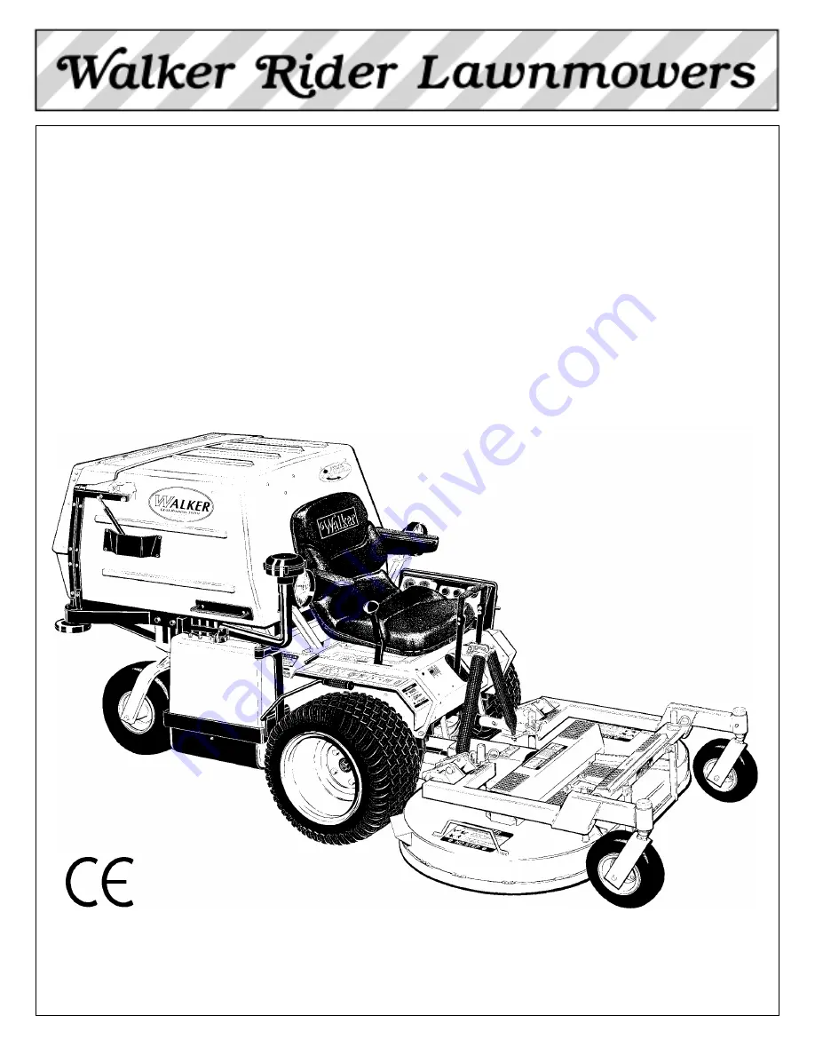
OWNER’S MANUAL

Safety, Assembly, Operating, and Maintenance Instructions

Model MDD (20.9 HP Diesel)

Please Read and Save These Instructions

Effective Date: 12-01-03

For Safety, Read All Safety and Operation 

P/N 7000-6

Instructions Prior to Operating Machine 

Price $5.00

Summary of Contents for MDD (20.9 HP)

Page 1: ...Operating and Maintenance Instructions Model MDD 20 9 HP Diesel Please Read and Save These Instructions Effective Date 12 01 03 For Safety Read All Safety and Operation P N 7000 6 Instructions Prior t...

Page 2: ...ant to your safety and must be read and understood to help prevent possible injury to the operator or others If anything in this manual is confusing or hard to understand please call our service depar...

Page 3: ...stallation on Tractor ______ 20 Deck Installation ____________________ 20 Deck Leveling ______________________ 22 PREOPERATING CHECKLIST ____________ 23 Operating Instructions_____________ 25 CONTROL...

Page 4: ...Blades ________________ 62 Drive Belts __________________________ 63 Mower Deck Gearbox Oil Seals _________ 63 Fuel Lines and Clamps ________________ 64 Radiator Hoses and Clamps ____________ 64 Engi...

Page 5: ...ain wheels HYDROSTATIC TRANSMISSION transmits and controls power from the ground drive belt to the main drive wheel LEFT HAND LH refers to the left hand side of the tractor when the operator is seated...

Page 6: ...components during the limited warranty period it is important to find a local authorized servicing agent of the component manu facturer Any unauthorized work done on these components during the warra...

Page 7: ...Fan Electric radiator cooling fan with reversible self cleaning action Coolant 50 50 Pre Mix Antifreeze Water ELECTRICAL SYSTEM Battery 12 Volt 41AH 340 CCA Interstate U1 SP40 Charging System Automot...

Page 8: ...ely Variable 0 5 0 8 Infinitely Variable BLADE DRIVE PTO Shaft Quick Disconnect Spline Shaft with Two High Speed U Joints Blade Spindle Each Blade 2 Mounts Direct on Peerless Right Angle Gearbox with...

Page 9: ...cm Center Overlap Two Blades Counter Rotate Deck Suspension Torsion Flex Frame with Caster Wheels and Counterweight Springs CURB WEIGHT Approximate SD Tractor Only 760 lb 345 kg GHS Tractor Only 850...

Page 10: ...els Optional Grass Catcher Capacity 89 Gallons 335 liters 9 5 Bushels Full Signal Oscillating Vane Switch Mounted on Grass Delivery Spout Triggers Horn Signal Powerfil Oscillating Delivery Spout Drive...

Page 11: ...Spring and Protective Cover Deck Support Pins and Height Adjustment Hitch Pins Anti Scuff Roller Transmission Control Rod Adjustment Nut RH Deck Lift Handle Cutting Height Adjustment Tilt Up Hook Foot...

Page 12: ...her Door Gas Spring Removable Grass Catcher Screen Not Visible Catcher Exhaust Deflector Catcher Door Catcher Door Handle Dump Plate Anti Scuff Roller Coolant Recovery Tank Radiator Screen Radiator Gu...

Page 13: ...ve Battery Cable Air Restriction Indicator Not Visible Precleaner Tube Jackshaft PTO Gearbox Dipstick Turbine Precleaner RH Transmission Lockout Lever 40 Amp Circuit Breaker PTO Clutch Lever 30 Amp Ci...

Page 14: ...d Thermostat Radiator Screen Removable Radiator Fan and Shield Engine Stop Lever Linkage Fuel Shut Off Valve Throttle Control Linkage Lever Injection Pump Injectors Air Intake Hose Fuel Tank Cap Fuel...

Page 15: ...tact your authorized Walker Mower Dealer or call Walker Manufacturing Company at 970 221 5614 BEFORE OPERATING 1 Read and understand the contents of this Owner s Manual before starting and operat ing...

Page 16: ...the engine 11 Never attempt to make any adjustments while the engine is running except where specifically instructed to do so 12 The electrical system battery contains sulfuric acid Avoid any contact...

Page 17: ...ion or with the back door OPEN Dan gerous projectiles may be thrown out of the dis charge chute or the back of the grass catcher 17 For GHS equipped models use care when closing the grass catcher door...

Page 18: ...to adjust a pump injector nozzle or any part of the fuel injection system 8 Altering the equipment or engine in any manner which adversely affects its operation perfor mance durability or use will VO...

Page 19: ...Latch Release 7820 Rear Cross Member of Front Body 8825 Rear of Grass Catcher Exhaust Screen 5869 SAFETY CONTROL AND INSTRUCTION DECALS Safety Control and Instruction Decals are installed on the machi...

Page 20: ...Adjacent to Dipstick 7827 Gear Axle 5810 1 Deck Gearbox Cover 5807 3 SAFETY CONTROL AND INSTRUCTION DECALS Safety Control and Instruction Decals are installed on the machine if any are missing illegi...

Page 21: ...Battery Service Ifthebatteryhasbeenshippedwet buttheelectrolyte level is low or the battery needs to be charged then 1 Fill each battery cell with drinking water to the bottom of the vent wells 2 Cha...

Page 22: ...Battery Installation Mower Deck Assembly Deck Caster Wheels Installation 1 Remove the bolt nut axle spacer tube and spacer washers from each deck caster wheel fork NOTE Spacer washers are used only w...

Page 23: ...tion Side Discharge Models Only Attach the deck side discharge shield by positioning the shield hinge lug in front of the deck mount and fastening with two 3 8 16 x 1 1 4 in bolts 3 8 16 ESNA nuts and...

Page 24: ...guiding the deck chute into the blower 4 Install the hitch pin through the hole on the end of each support arm to lock the deck in place refer to Deck Counterweight Spring Installa tion photo Two 2 hi...

Page 25: ...to 25 Ib 7 to 11 kg Check this weight by lift ing on the front of the deck carrier frame If required the spring tension can be adjusted by tightening or loosening the elastic stop nuts located undern...

Page 26: ...3 Check the front to rear level Rotate the blades to point forward Measure the distance from blade tip to ground on the front and rear The rear of the blade should be 1 8 to 1 4 in 3 to 6 mm higher t...

Page 27: ...SYSTEM Check air restriction gauge to make sure there is no red indication showing Check condition cleanliness and security of the complete air cleaner system clean air filter every 100 hours For deta...

Page 28: ...nto the tilt up latch on the tractor body Before operating the tractor make sure to re engage the deck lock levers after lowering the deck to the normal operating po sition Deck Secured in TILT UP Pos...

Page 29: ...n increases engine speed moving it back ward toward the IDLE position decreases engine speed Throttle Location CAUTION Before operating the mower become fa miliar with the location and function of all...

Page 30: ...ound travel NOTE Pushing forward on the steering levers will not cause any change in tractor motion there will be no steering lever reaction and there will be no machine damage Blade Clutch PTO The bl...

Page 31: ...ction for operating instructions Lockout Lever Location NOTE The transmission plunger on the side of the transmission case activated by the LOCKOUT LE VER must be completely released during operation...

Page 32: ...tablishes the Neutral Park Position of the Steering Levers FORWARD SPEED CONTROL LEVER FSC Full Forward Ground Speed Position Intermediate Ground Speed Position Neutral Park Position Disengaged Positi...

Page 33: ...e instrument panel Light Switch Optional Hourmeter Circuit Breaker 10 Amp Headlights Safety Interlock Switch System Fuel Solenoid Hold Powerfil Motor GHS Only Full Signal Horn GHS Only Circuit Breaker...

Page 34: ...ay be a problem with Radiator cooling air flow material packed into radiator cooling fins clogged air intake screen Low coolant quantity in cooling system Engine fan belt Thermostat function Stop the...

Page 35: ...ED NOTE Release parking brake to prevent extra load on the starter if the transmission neutral is slightly out of adjustment NOTE For starting in cold weather below 40 F 4 C use the cold start lever t...

Page 36: ...e engine cranks but does not start check the following The fuel valve solenoid is operating Look at the exhaust pipe when cranking the engine no smoke indicates no fuel is reaching the cylinder If the...

Page 37: ...k during operation and if the machine is on a slope the machine will freewheel down the slope To maintain control immediately 1 Release the steering levers and simultaneously 2 Move the FSC to the NEU...

Page 38: ...ten drive belt life Use only moderate engine speed when engaging the blade clutch 2 Pull the blade clutch lever SLOWLY up to engage the mower blades IMPORTANT DO NOT engage the blade clutch when trans...

Page 39: ...to ENGAGE the parking BRAKE to prevent the mower from creeping This is due to a small amount of slip page in the hydrostatic transmissions especially when transmission fluid is warm ADJUSTING CUTTING...

Page 40: ...hydrostatic transmissions are unlocked released 1 Raise the front body 2 Lift the transmission lockout lever on both the RH and LH transmissions and secure into place with the locking cam 3 The mower...

Page 41: ...Assembly Instructions Use an alternating stripe mowing pattern for best appearance and vary the direction of the stripe each time the grass is mowed to avoid wear patterns in the grass Avoid damage to...

Page 42: ...ody should never be tilted for ward with the deck in the tilt up position This can cause the deck to unhook from the tractor and fall with considerable force potentially causing deck or tractor damage...

Page 43: ...ck Discharge Chute Blower Body Chute Assembly Powerfil Delivery Spout Dump Handle Grass Catcher Catcher Door Exhaust Deflector Grass Pak Vane Switch Exhaust Screen Removable Catcher Door Safety Latch...

Page 44: ...tions NOTE In Autumn when using the GHS mower to vacuum leaves it is recommended to raise the front of the mower deck 2 to 3 notches 1 to 1 1 2 in 25 to 38 mm higher than the rear This will avoid bull...

Page 45: ...ably clean and free of grass and dirt buildup While some degree of material buildup can be tolerated a point is finally reached where the flow of air and grass clippings is restricted NOTE One conditi...

Page 46: ...gnition switch ON engaging the blade clutch engine not running opening the catcher back door and triggering the Grass Pak vane by hand as it oscillates The horn should sound as the switch is moved in...

Page 47: ...the normal operating position DO NOT allow the catcher to drop down 4 Close the door by holding the door handle with the left hand and releasing the safety latch on the door hinge mechanism with the...

Page 48: ...hile sitting in the seat A toggle switch operating a power ram is used to raise and lower the catcher The back door automatically opens and closes during the dump cycle Hold the toggle switch UP or DO...

Page 49: ...Power Dump Ram Actuator Rear Body Panel RH Lift Channel Cable Guide Grass Catcher Door Actuator Arm Catcher Door Gas Spring Catcher Door Cable Rod Guide Cable Assembly Rear Body Panel LH Gas Spring Ac...

Page 50: ...k Adjust Blade Clutch PTO Brake Action x 78 Check Oil Level in Gear Axle x 53 Clean Hydrostatic Transmission Cooling Fins x 60 Change Engine Oil Filter x 48 Check Radiator Hoses and Clamps x 64 Check...

Page 51: ...will allow the engine to produce full horsepower and move more cooling air through the radiator Air Cleaner System Use only Donaldson air cleaner elements After market elements may not seal in the ai...

Page 52: ...he oil lev el on the dipstick The oil level should be within the Operating Range on the dipstick between the lower mark and the upper mark IMPORTANT DO NOT operate engine without a sufficient oil supp...

Page 53: ...ty will aid starting in cold weather and as sure proper lubrication in hot weather Fill up to but not above the upper mark on the dip stick Crankcase capacity is 3 1 quarts 2 9 li ters plus 1 2 pint 2...

Page 54: ...ound Drive 23 PTO Clutch Lever Pivot Grease 1 24 Clutch Actuator Push Rod Grease 2 UDNH FWXDWRU 5RG DQG UDNH 2LO Band Pivot Pins Clevis 26 Idler Arm Oil 1 27 Engine Belt Idler Pulley Oil 1 28 Throttle...

Page 55: ...ctions LUBRICATION 51 13 2 2 3 4 4 15 15 16 16 14 14 10 11 12 13 18 19 17 21 21 23 24 25 22 20 27 28 29 28 38 26 30 30 31 31 32 34 33 36 37 37 35 33 34 39 40 1 1 5 6 8 8 9 9 7 7 7 7 Chassis and Deck L...

Page 56: ...is low add SAE E P Extreme Pressure 90W oil until the oil level is up to sub merges the horizontal shaft in the gearbox shaft parallel to cover plate NOTE In case the gearboxes are completely drained...

Page 57: ...x to avoid oil leakage out of the dipstick standpipe If the oil level is low check the gearbox for any indi cation of an oil leak If an oil leak is noted the gear box will need to be removed and rebui...

Page 58: ...flu id refer to Specifications for the proper fluid As soon as there is fluid leaking from around the air bleed plug tighten the plug and fill the reservoir to the COLD level mark Wipe any excess oil...

Page 59: ...fill the reser voir with fluid allowing a small amount to leak out of the air bleed plug hole 7 Install the air bleed plug and fill the reservoir to the COLD level line CLEANING Engine Air Cleaner Sys...

Page 60: ...t leaks due to improper filter installation Intake design internal baffling and a Vacuator valve provide dust separation and auto matic precleaning action Daily or frequent servicing of the air cleane...

Page 61: ...ling surface inside of the open end of the filter Replace the filter if any cracks tears or other damage to the sealing surface are noted 6 Use a clean damp cloth and wipe the interior of the air clea...

Page 62: ...al for lo cation of the drain cocks Also drain the cool ant recovery tank 3 If there is any indication of deposits or scaling inside the radiator use a commercial scale re mover and flush the cooling...

Page 63: ...n the tightener arm Roll the belt off the blower pulley The belt should be clear of the blower pulley allowing free movement of the blower wheel IMPORTANT With the belt removed the blow er wheel must...

Page 64: ...an oil leak develops on the input shaft the cooling fan blowing dusty air and oil on the transmission will quickly pack the cooling fins with oily dirt If this condition occurs replace the seal immedi...

Page 65: ...he follow ing items should be inspected 1 Check the Donaldson Radialseal air cleaner canister for damage Make sure the cover is in place and the cover latches are secure do not run the engine without...

Page 66: ...d dis connect the electrical plug on the fuel shut off solenoid before raising the mower deck to ser vice blades 2 Raise the deck and secure it in the TILT UP po sition Refer to CLEANING the Grass Bui...

Page 67: ...Clogging Checklist in Operating Instructions for correct blade rotation Drive Belts Raise the body and inspect the condition of the five 5 belts 4 belts on SD models every 25 hours of operation engine...

Page 68: ...Check and adjust the Kubota diesel engine fuel in jection nozzle pressure yearly or every 1000 hours or in case of low power Refer to the Kubota Work shop Manual for specifications and procedures to...

Page 69: ...uickly the blades stop Watch the rotation of the blade drive shaft and blower pulley as a visual indication that movement has stopped If the brake is working properly all rotation will stop five 5 sec...

Page 70: ...Maintenance Instructions REPLACING REPAIRING 66 Jackshaft Drive Belt Engine PTO Belt Engine Fan Belt GHS Blower Belt GHS Model Only Hydrostatic Ground Drive Belt Belt Locations...

Page 71: ...axi mum looseness of the belt to assist removal c Remove the PTO drive belt by walking the belt off of the engine and PTO pulleys one groove at a time until the belt is com pletely removed 2 Install t...

Page 72: ...Released Engine Pulley Ground Drive Idler Pulley Disengaged Jackshaft Pulley Jackshaft Drive Belt Idler Arm Release b Slide the idler arm release down to unlock the idler arm from the spring lever Th...

Page 73: ...lley The belt should be clear of the blower pulley allowing free movement of the blower wheel Blower Pulley Blower Drive Pulley GHS Blower Drive Belt Belt Tightener Idler Pulley Disengaged Idler Pulle...

Page 74: ...belt b Slide belt off pulleys then release the idler Transmission Drive Pulley Spring Idler Pulley Jackshaft Belt Tightener Arm Hydrostatic Ground Drive Belt Hydrostatic Ground Drive Belt Assembly Di...

Page 75: ...relax and remove belt Alternator Bracket Crankshaft Pulley Engine Fan Belt Tensioner Bolt Water Pump Pulley Alternator Engine Fan Belt Loose 2 Reverse the procedure to install the belt Ad just and che...

Page 76: ...olts NOTE Shear bolts are not used on the DSD62 mower deck The cutting blade is keyed to the blade hub by two 2 shear bolts 10 24 x 5 8 in stainless steel ma chine screws These bolts are designed to s...

Page 77: ...course of sharpening and inspecting mower blades if there are any of the following conditions of wear or damage blades should be replaced for reasons of safety and performance of the machine An excess...

Page 78: ...assembled and thoroughly flushed out with solvent before reassembly 5 Drain and properly dispose of oil 6 Remove the four 4 bolts mounting the gearbox to the connector tube and slide the gearbox off t...

Page 79: ...own out of the chassis frame and remove Blower Wheel Removal When required replace the blower wheel using the following procedure 1 Loosen blower pulley set screws and remove the pulley using a wheel...

Page 80: ...tall the blower assembly into the mower using the reverse procedures of GHS Blower Assembly Removal Replacing Fuel Valve Solenoid For checking operation of the solenoid refer to CHECKING SERVICING the...

Page 81: ...Speed Control FSC and or the PTO engaged With an operator in the seat the engine starts but dies soon after the Forward Speed Control FSC or PTO is engaged Without an operator on the seat the engine...

Page 82: ...ng a Check clearance between the clutch idler pulley and the motor mount when the pulley is in the declutched position If there is no clearance and the idler pulley rests on the frame the blade brake...

Page 83: ...ight Ground Travel Adjustment Step 4 IMPORTANT The following adjustment procedures are sequential Check and adjust each function in the order given Set Forward Travel Limit Stop Step 1 1 Move the Forw...

Page 84: ...ionary since the differential adjustment has not been made This is covered by the Straight Ground Travel Adjustment Step 4 In this case the neutral adjustment should be made for one wheel stationary a...

Page 85: ...riction adjust ment nut Loosen or tighten the nut and check the control function until conditions of both steps 1 and 2 above are met Tilt Up Deck Adjustable Stop When the carrier frame hinge joint is...

Page 86: ...tions apply Troubleshooting When Horn Fails to Operate 1 Check the horn a Disconnect the two wires from the Grass Pak switch electric connector plug and make a jumper wire connection between these wi...

Page 87: ...l Circuit Breakers Location Reset Amperage Circuits Electrical Load Master Circuit Breaker Mounted on Bracket Behind Battery 40 AMP Instrument Panel Starter Solenoid Glow Plugs Pull Circuit Fuel Valve...

Page 88: ...T BREAKER RED RED RED RED RED RED BLU RED BLK BRN BRN RED FOR TAIL WHEEL LOCK BRN RED ORG GRA WATER LIGHT TEMP YEL RED YEL RED ORG WHT RELAY B RELAY A RELAY E ORG 85 30 86 87 87A ORG YEL IGNITION PUR...

Page 89: ...BBBBBBBBBBBB BBBBBBBBBBBBBBBBBBBBBBBBBBBBBBBBBBBBBBBBBBBBBBBBBBBBBBBBBBBBBBBBBBBBBBBBBBBBBBBBBBBBBBBBBBBBBBBBBBBBBBBBBBBBBB BBBBBBBBBBBBBBBBBBBBBBBBBBBBBBBBBBBBBBBBBBBBBBBBBBBBBBBBBBBBBBBBBBBBBBBBBBBB...

Page 90: ...86 Operator s Notes...

Page 91: ...in the Owner s Manual for operation and maintenance B The customer shall pay any charges for making service calls and or for transporting the mower to and from the place where the inspection and or w...

Page 92: ...rature 32 F o 0 C o Wind Speed 5 mph 8 kmh Humidity 58 BarometricPressure 25 0 HG 636mmHg Lwa 105 LpA 93 OPERATOR Vibration Model MDD Vibration Level Vibration levels at the operators handles were mea...

Reviews: