P.10
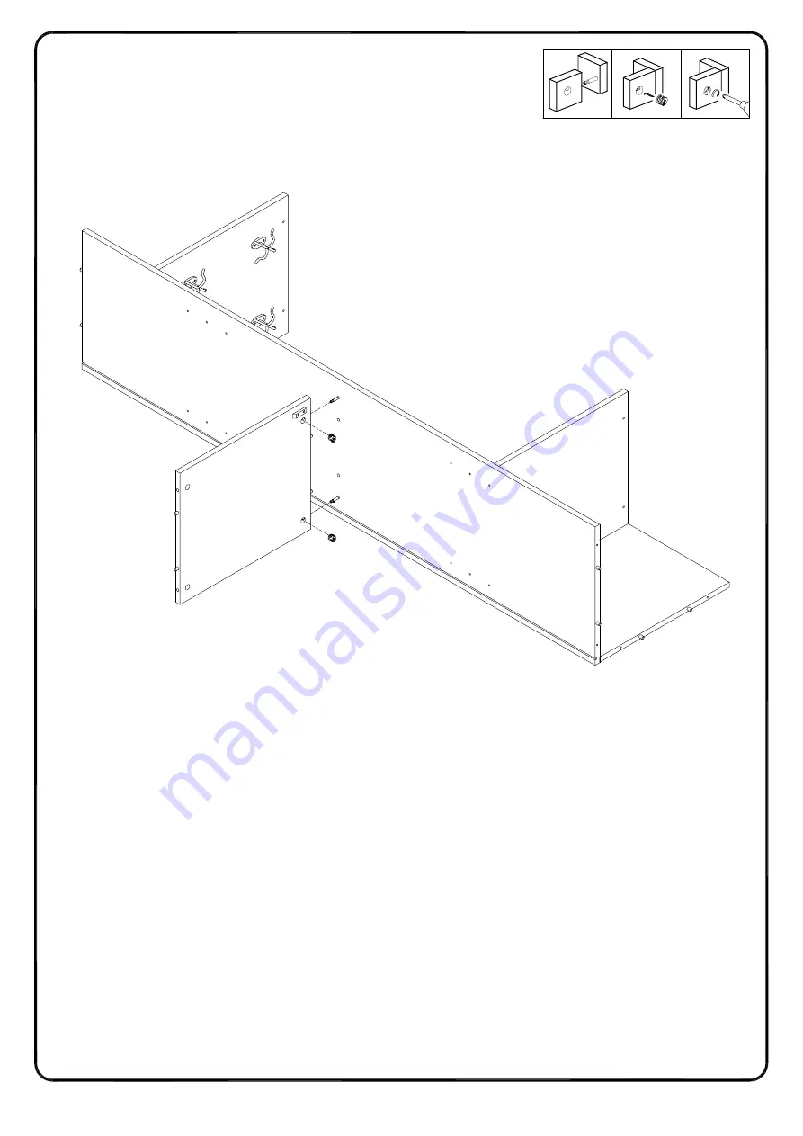
Step 6
2
1
3
4
C
14
Using cam lock (C) attach part (14) to part (4) with Philips head screwdriver as per diagram.
Page 1: ...P 1 ...
Page 2: ...e hole and insert the dowel Wipe away excess glue immediately In future assembly steps when dowels are necessary to attach assembly parts together place a small amount of glue on the end of the dowel before attaching parts together Wipe away excess glue immediately VI A Phillips head screwdriver is required for the assembly of this product VII Power tools should not be used to assemble this produc...
Page 3: ...Parts List P 3 1 2 3 4 5 6 7 8 9 10 11 12 13 14 13 15 15 ...
Page 4: ...m lock 12 pcs C Ø30mm Sticker D Ø6x50mm Screw 12 pcs E 10 pcs F 10 pcs G Ø3x17mm Screw 10 pcs H Handle 2 pcs J Ø4x22mm Bolt 4 pcs K 4mm Hex Key 1 pc L Glue tube 1 pc M N Screw 24 pcs P Q Ø3 5x14mm Plastic wedge Bolt R Ø6x12mm Hardware List Hook Europe Hinge Shelf support pin Velcro strap Screw Nut Screw Ø4x25mm Ø4x12mm 2 pcs 2 pcs 2 pcs 2 pcs S T U V W X Bolt Ø6x25mm 4 pcs 4 pcs 8 pcs 12 pcs 4 pcs...
Page 5: ...P 5 Step 1 3 B B A A A A Insert wooden dowel A into part 3 then secure cam bolt B into part 3 with Philips head screwdriver as per diagram ...
Page 6: ...P 6 Step 2 4 4 B B B B B B B B A A A A Insert wooden dowel A into part 4 then secure cam bolt B into two sides of part 4 with Philips head screwdriver as per diagram ...
Page 7: ...5 12 S S S S S R Insert wooden dowel A into parts 9 14 using screw black P attach hook M to part 9 Door stopper N to parts 1 14 with Philips head screwdriver using bolts S T attach part 15 to part 2 using bolt S attach part 12 to part 2 with hex key R as per diagram ...
Page 8: ... 8 2 1 3 A A A A A A A A B B 11 10 10 11 C C Insert wooden dowel A into parts 10 11 Secure cam bolt B into part 10 then using cam lock C attach part 11 into part 10 with Philips head screwdriver as per diagram ...
Page 9: ...P 9 Step 5 2 1 3 C C C C C C 4 9 10 11 Using cam lock C attach parts 9 10 11 to part 4 with Philips head screwdriver as per diagram ...
Page 10: ...P 10 Step 6 2 1 3 4 C C 14 Using cam lock C attach part 14 to part 4 with Philips head screwdriver as per diagram ...
Page 11: ...Step 7 P 11 2 1 3 C C 14 3 Using cam lock C attach part 14 to part 3 with Philips head screwdriver as per diagram ...
Page 12: ...Step 8 P 12 3 4 11 2 R E E E E E E Using screw E attach part 2 into parts 3 4 11 with hex key R as per diagram ...
Page 13: ...Step 9 P 13 R 2 10 9 5 S S S S S S S R Using bolt S attach part 5 to parts 2 9 10 with hex key R as per diagram ...
Page 14: ...Step 10 P 14 6 4 3 Put part 6 as per diagram ...
Page 15: ...p 11 P 15 4 3 5 1 T T R E E E E R Using bolt T E attach part 1 into part 3 4 5 with hex key R as per diagram please kindly note that keep the back panel into the groove of part 1 then secure all the bolts ...
Page 16: ...Step 12 P 16 D D D D D Place sticker D cover the holes as per diagram ...
Page 17: ...Step 13 P 17 1 U X U X Using screw X attach Velcro strap U into part 1 with Philips head screwdriver as per diagram ...
Page 18: ...Step 14 P 18 6 F F G Using screw G secure plastic wedge F into part 6 with Philips head screwdriver as per diagram ...
Page 19: ...helf support pin Q into parts 3 4 as per diagram Make sure you place the four shelf support pins Q in the same level So the shelf is not titled Put part 13 into unit as per diagram Tilt and rest the adjustable shelf 13 onto the shelf support pins ...
Page 20: ...Step 16 P 20 8 7 H H J J J J K K K K L L L L L L L L Using bolt J attach handle H into parts 7 8 and using screw L attach Europe hinge K to parts 7 8 with Philips head screwdriver as per diagram ...
Page 21: ... K K K K L L L L K L Using screw L attach Europe hinge K to part 3 with Philips head screwdriver as per diagram Open and close the doors to make sure they were shut correctly if necessary adjust the screws for a good fit ...
Page 22: ...permanently fixed to the wall Wall anchor and hardware are included with this product Please make sure hardware is suitable for your walls before installing as different wall materials may require different types of anchors Wall P 22 WARNING W U V Using screw V attach Velcro strap U into Nut W to Wall with Philips head screwdriver as per diagram ...
Page 23: ...Step 19 P 23 Position the assembled unit at the desired location if necessary adjust the floor leveler at the bottom of support leg to level the unit ...
Page 24: ...Final Assembly Step 20 P 24 ...