46
47
6.0 MAINTENANCE
The controller itself requires very little maintenance. Wipe with a damp cloth. Do not spray down the controller unless
the enclosure door is closed and latched.
6.1 Conductivity Sensor Cleaning
NOTE: The controller must be recalibrated after cleaning the sensor.
Frequency
The sensor should be cleaned periodically. The frequency required will vary by installation. In a new installation, it is
recommended that the sensor be cleaned after two weeks of service. Electrodeless conductivity sensors are much less
sensitive to coatings and should go longer between cleanings. To determine how often the sensor must be cleaned, fol-
low the procedure below.
1. Read and record the conductivity.
2. Remove, clean and replace the conductivity sensor.
3. Read conductivity and compare with the reading in step 1 above.
If the variance in readings is greater than 5%, increase the frequency of sensor cleaning. If there is less than 5% change
in the reading, the sensor was not dirty and can be cleaned less often.
Cleaning Procedure
The sensor can normally be cleaned using a cloth or paper towel and a mild detergent. If coated with scale, clean with
a dilute (5%) solution of hydrochloric acid solution.
Occasionally an electrode may become coated with various substances that require a more vigorous cleaning procedure.
Usually the coating will be visible, but not always.
To clean a severely coated electrodeless conductivity sensor, scrub with a toothbrush or stiff bottlebrush. Soap or hand
cleaner may help. If coated with scale, clean with a dilute (5%) hydrochloric acid solution. Harsh abrasives should be
avoided. Rinse the sensor thoroughly before returning to service.
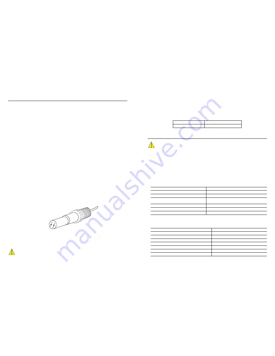
To clean a severely coated flat surface cooling tower electrode, use fine grit abrasive, such as emery paper. Lay the paper
on a flat surface and move the electrode in a back and forth motion. The electrode should be cleaned parallel to the carbon
electrodes, not perpendicular.
Clean in this
direction
Figure 14 Cleaning a flat contacting conductivity electrode
Replacing the Fuse
CAUTION: Disconnect power to the controller before opening front panel!
Models that include powered relays have a fuse to protect the controller from devices connected to the relays that
draw excessive current. Locate the fuse on the circuit board at the back of the controller enclosure, underneath the
clear cover (see figure 7). Gently remove the old fuse from its retaining clip and discard. Press the new fuse into
the clip, replace the clear cover, secure the front panel of the controller and return power to the unit.
Warning: Use of non-approved fuses can affect product safety approvals.
Specifications are shown below. To
insure product safety certifications are maintained, it is recommended that a Walchem fuse be used.
F1 Fuse
Walchem P/N
5 x 20 mm, 6.3A, 250V
102834
7.0 TROUBLESHOOTING
CAUTION: Disconnect power to the controller before opening front panel!
Troubleshooting and repair of a malfunctioning controller should only be attempted by qualified personnel using caution
to ensure safety and limit unnecessary further damage. Contact the factory.
7.1 Calibration Failure
Calibrations will fail if the adjustments to the reading are outside of the normal range for a properly functioning system.
Refer to the instruction manual for the specific sensor being used for further information.
7.1.1 Contacting Conductivity Sensors
The calibration will fail if the adjustment to the gain is outside of 0.5 to 2.0.
Possible Cause
Corrective Action
Dirty electrode
Clean electrode
Improper wiring of sensor to controller
Correct wiring
Wrong cell constant entered
Program the controller cell constant setting at the value
that matches the electrode being used
Incorrect temperature reading or setting
Ensure that the temperature is accurate
Incorrect cable length or wire gauge setting
Set to the correct values
Faulty electrode
Replace electrode
7.1.2 Electrodeless Conductivity Sensors
The calibration will fail if the adjustment to the gain is outside of 0.2 to 10, or the offset is outside of -10,000 to
10,000.
Possible Cause
Corrective Action
Dirty sensor
Clean sensor
Improper wiring of sensor to controller
Correct wiring
Sensor placed too close to container walls
Relocate sensor
Sensor placed in the direct path of electrical current flow
Relocate sensor
Incorrect temperature reading or setting
Ensure that the temperature is accurate
Incorrect cable length or wire gauge setting
Set to the correct values
Faulty sensor
Replace sensor


