background image


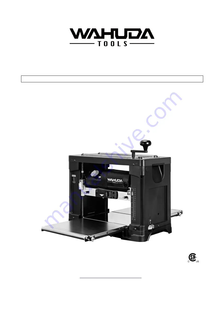
User Manual 


Read this manual before using machine to avoid serious injury and damage 


50200PC-WHD 


13” 2-Speed Portable Planer 

With Spiral Style Cutterhead and 4-Sided Carbide Inserts 


For technical support, email 

[email protected] 

  or call at 

877-568-8879


VER. 08.31.20


Summary of Contents for 50200PC-WHD

Page 1: ...sing machine to avoid serious injury and damage 50200PC WHD 13 2 Speed Portable Planer With Spiral Style Cutterhead and 4 Sided Carbide Inserts For technical support email techservices wahudatools com...

Page 2: ...ting 28 SECTION 14 Parts Diagram List 29 INTRODUCTION This user manual is intended for use by anyone working with this machine It should be kept available for immediate reference so that all operation...

Page 3: ...ight prepaid to WAHUDA s Authorized Service Center for inspection If the warranty claim is considered to be invalid due to exclusions listed above WAHUDA will at your direction dispose of or return th...

Page 4: ...ngth of Stock 9 1 2 Minimum Thickness of Stock 1 8 Carbide cutter inserts qty 26 4 sided Motor power input 120 V 60 Hz AC Only 15 Amp Shipping Weight 76 lbs Net Weight 65 lbs Shipping Dimensions 25 2...

Page 5: ...ury including silicosis a serious lung disease cancer and death Avoid breathing the dust and avoid prolonged contact with dust The dust may contain chemicals known to the State of California to cause...

Page 6: ...r quality job by only performing operations for which the machine was intended WARNING DO NOT stand on a machine Serious injury could result if it tips over or you accidentally contact any moving part...

Page 7: ...may result in serious personal injury WARNING USE ONLY recommended accessories Use of incorrect or improper accessories could cause serious injury to the operator and cause damage to the machine If i...

Page 8: ...d Health Regulations OSHA All electrical connections and wiring should be made by qualified personnel only 4 WARNING TO REDUCE the risk of electrical shock DO NOT use this machine outdoors DO NOT expo...

Page 9: ...erly adjusted prior to use 20 DO NOT try and remove excessive amounts of wood in one single pass 21 INSPECT all stock before beginning operations ensuring that there are no foreign objects embedded in...

Page 10: ...u are not sure the tool is properly grounded WARNING Electrocution or fire could result if this machine is not grounded properly or if the electrical configuration does not comply with local and state...

Page 11: ...or have it repaired by a qualified person before using it Protect your extension cords from sharp objects excessive heat and damp or wet areas MINIMUM RECOMMENDED GAUGE FOR EXTENSION CORDS AWG 115 VOL...

Page 12: ...be removed by wiping the surfaces with a soft cloth NOTE See later instructions for cleaning the cutterhead and insert tips which may be required before operation NOTE Some parts pictured may already...

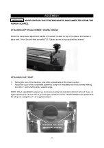
Page 13: ...upplied hex wrench ATTACHING DUST PORT 1 Facing the rear of the machine place the outfeed table in the down position 2 Attach the dust on the cutterhead assembly using 4 of the plastic star knob screw...

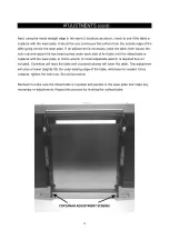
Page 14: ...TS ARE MADE WARNING BE VERY CAREFUL WORKING NEAR THE CUTTERHEAD INSERT TIPS THEY ARE EXTREMELY SHARP AND CAN CAUSE INJURY LEVELING INFEED AND OUTFEED TABLES The infeed and outfeed tables must be paral...

Page 15: ...der each side of the table until the infeed table is coplanar with the wear plate A 10mm wrench or small adjustable wrench is required but not included Clockwise will raise the table and counterclockw...

Page 16: ...extensions to their outward position 2 Lay your metal straight edge on one side of the infeed table and out over the extension rod 3 If the end of the extension rod is not level with the table using t...

Page 17: ...over from the process Removal of this oil residue if apparent should be done before you use your new machine 1 Place the machine at a comfortable working height and supply ample lighting 2 Facing the...

Page 18: ...e excess oil off the threads 11 Place each insert tip in the seat and slightly snug each screw using the Hex Wrench to hold the cutterhead in position Once you get a row of tips seated and slightly ti...

Page 19: ...A TABLE OR WORKBENCH During operation the planer MUST be secured to a supporting surface such as a solid and sturdy workbench or table Four holes are provided 2 are shown below to securely mount the p...

Page 20: ...DAMAGE THE SPEED MECHANISM RAISING AND LOWERING HEAD ASSEMBLY The cutterhead assembly consists of the cutterhead insert tips feed rollers roller chains gearbox and cutterhead dust chute Raising and lo...

Page 21: ...nserted completely and a faint click is felt DEPTH OF CUT INDICATOR The Depth Of Cut Indicator located on the front of the machine is a convenient way to quickly determine how much material is being p...

Page 22: ...e to do so may result in excess downward pressure by the cutterhead assembly onto the mechanism and cause damage to the adjustment rod and upper frame THICKNESS SCALE ADJUSTMENT The thickness scale lo...

Page 23: ...If an object is thrown from the planer it can travel in either direction 1 Stand to either the left or right side of the planer 2 Flip the switch to the ON position 3 Once powered on select desired f...

Page 24: ...aned to avoid this problem Since snipe can occur at both ends of the board it is good practice to start with a workpiece that is slightly longer than what you need so that you can simply cut off the e...

Page 25: ...ulation The operator should always wear a respirator and eye protection when using compressed air Do not allow chips and dust to accumulate under the machine Keep area clean and in safe order Having c...

Page 26: ...ove the top cover 3 On the left side panel remove the 4 socket head screws located around the bottom edge and remove the side panel to expose the gearbox 4 Remove the gearbox cover and lube the gears...

Page 27: ...The other is located in the same position on the rear of the motor assembly The Brush Holder can be removed using a flat blade screwdriver 2 Once the brush has been removed inspect the carbon B the s...

Page 28: ...d moisture content Dull blades Too deep a blade setting Dry wood before planing Replace or turn blades Reduce depth of cut Board thickness does not match depth scale indicator Depth scale incorrectly...

Page 29: ...29 PARTS...

Page 30: ...13 Leader Screw Driver side 1 50200 A14 Leader Screw Driver side 3 50200 A15 Aside Cover Right 1 50200 A16 Cutting Scale 1 50200 A17 Screw M6x18 1 50200 A18 Cutting Thickness Gauge 1 50200 A19 Steel B...

Page 31: ...rew M8x10 2 50200 A46 Socket Head Cap Screw M4x 10 4 50200 A47 Lock Washer M4 12 50200 A48 Flat Head Screw M3x25 2 50200 A49 Flat Washer M4 4 50200 A50 Spacer M10 4 50200 A51 Spacer M12 4 50200 A52 Ex...

Page 32: ...32...

Page 33: ...50200 B17 Spring 1 50200 B18 Steel Ball 8 1 50200 B19 Speed Adjustment Shaft 1 50200 B20 S Ring S 8 1 50200 B21 Handle 1 50200 B22 Socket Head Cap Screw M4x12 1 50200 B23 Bracket included 4 16 1 50200...

Page 34: ...8 1 50200 B55 Pointer 1 50200 B56 Dust Chute 1 50200 B57 Clamp 2 50200 B58 Socket Round Head Screw M5x12 2 50200 B59 Flat Washer M4 1 50200 B59 1 Flat Washer 8 D15 1 50200 B59 2 Flat Washer M4 1 50200...

Page 35: ...Washer M4 2 50200 B82 Flat Washer M3 1 50200 B83 Socket Round Head Screw M3x10 1 50200 B84 Socket Head Button Screw M4x20 2 50200 B86 Set Screw M4x5 1 50200 B88 Flat Washer M8x2t 1 50200 B88 1 Flat W...

Page 36: ...36...

Page 37: ...ch Plate 1 50200 C6 Machine Screw M5x12 5 50200 C7 Switch 1 50200 C8 Motor Pulley 1 50200 C9 Flat Washer M5 2 50200 C10 Lock Washer M5 2 50200 C11 Socket Round Head Screw M5x16 1 50200 C12 Socket Roun...

Page 38: ...38...

Page 39: ...50200 D3 Socket Round Head Screw M5x10 3 50200 D4 Cutterhead 13 1 50200 D4A Pin Do not show 5 50200 D5 Bearing Seat 1 50200 D6 Spindle Pulley 1 50200 D7 Nut L H M16xP2 0 1 50200 D8 Insert 26 50200 D9...

Page 40: ...40...

Page 41: ...x22 4 50200 E03 Fixed block 4 50200 E04 Nylon Nut M5 12 50200 E05 Extension plate Right 2 50200 E06 Extension plate Left 2 50200 E07 Fixed rod 2 50200 E08 Set Screw M4 10 4 50200 E09 Fixed Plate 4 502...

Reviews: