750 XTR Series
Assembly and Disassembly
System manual | Version: 2.0.0
53
•
Do not forget bus termination:
Always plug an end module (item no.:
ü
or
ü
) onto the end of the fieldbus node! You
must always use this end module in all fieldbus nodes with XTR head stations of the
WAGO I/O System 750 XTR in order to guarantee proper data transfer!
7.2 Snapping the Head Station onto the DIN-Rail
1. When replacing a head station that is already present, position the new head station
so the groove and spring are connected to the following I/O module.
2. Snap the head station onto the DIN-rail.
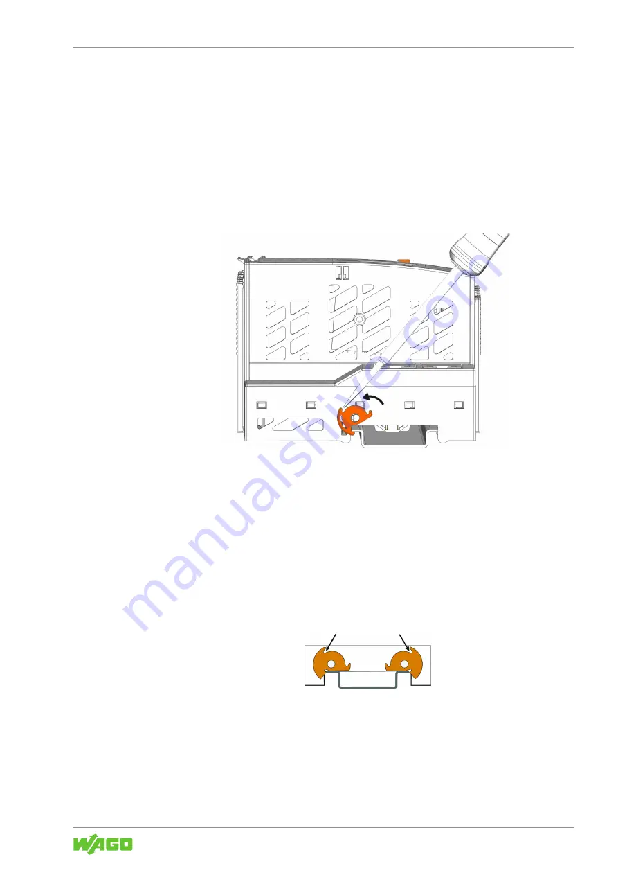
Figure 27: Locking the Head Station
3. Use an operating tool to turn the DIN-rail locking cam(s) until the nose of the respec-
tive DIN-rail locking cam engages behind the DIN-rail.
ð
This secures the head station against tilting on the DIN-rail.
ð
Once the head station has been snapped into place, the electrical connections for the
data contacts and power jumper contacts (if any) to the following I/O module are es-
tablished.
Special Case: Head Stations with Two DIN-Rail Locking Cams
Some head stations have two DIN-rail locking cams. In this case, the head station must
also be locked onto the DIN-rail with both DIN-rail locking cams.
7.3 Attaching an I/O Module
1. Position the I/O module in such a way that the grove and spring are connected to the
preceding and, if applicable, the following components.


