36
Process Image
WAGO-I/O-SYSTEM 750
750-657 IO-Link Master
Manual
Version 1.0.2, valid from FW/HW-Version 02/01
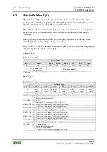
Output data:
The SIO byte is only applied when the associated process data segment has a
length of 0. Otherwise, the value is ignored in the SIO byte.
Process data that exceeds 1 bit per port is in the range of the cyclic data (see the
following section).
6.4
Cyclic Process Data
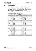
The following is an example of a Mailbox size of 2 bytes during configuration:
The first bytes of the process image are already allocated with the control/status
byte, the Mailbox bytes and the SIO byte.
If the selected internal bus data width is more than the set Mailbox size +
control/status and SIO byte, another data storage area is available in addition to
using the SIO byte in which process data is transferred cyclically from attached
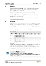
IO-Link devices (see the following figure).
Four segments can be configured in this area – one segment for each pot
available. The segment size is set based on the requirements of the application or
attached devices.
The figure shows the following application with a Mailbox set to 2 bytes:
•
Internal bus data width: 24 bytes
•
Segment size for port 1: 3 bytes
•
Segment size for port 2: 2 bytes
•
Segment size for port 3: 5 bytes
•
Segment size for port 4: 7 bytes

