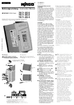
787-850
787-852
787-854
Schaltnetzteil
, dreiphasige, primär getaktete Einbaustromversorgung für
TH35-Schienenmontage
Primary switched mode supply,
three phase primary switched mode power supply
component for mounting on DIN 35 mm rails
Normen
Safety standards
Sicherheit
Safety
EN 60950, UL 60950, UL 508
EMV
EMC
EN 61204-3 (Produktnorm)
EN 61204-3 (product standard)
Schutzkleinspannung
Safety extra-low voltage
EN 60950 (SELV) und EN 60204 (PELV)
EN 60950 (SELV) and EN 60204 (PELV)
Zulassungen
Approvals
UL
UL
UL/CSA 60950 recognised
UL
UL
UL 508 listed / CSA 22.2 No.107.1 3rd Ed. listed
Umwelt
Environment
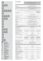
Umgebungstemperatur
Ambient temperature
–25° C … +70° C, Derating: -3 %/K > +50° C
–25° C … +55° C,
Derating: -5 %/K > +45° C
400 Vac ... 500 Vac,
Derating: -0,5 Adc/10 Vac >
440 Vac
Anlauf bei -40° C typgeprüft
Device start at -40° C type-tested
Lagertemperatur
Storage temperature
–25° C … +85° C
Kühlart
Cooling
Selbstkühlung durch natürliche Konvektion bei vertikaler Einbaulage
AN (Natural air convection cooling)
Zulässige Luftfeuchtigkeit
Allowable humidity
5 bis 96% relative Feuchte, keine Betauung zulässig
5 to 96% relative humidity with no dew
Sicherheit und Schutz
Safety and protection
Prüfspannung
HV test voltage
4,2 kVdc
Bauart
Construction
gekapselt, für den Einbau im Schaltschrank
enclosed for installation in switching cabinets
Schutzart
Protection index
IP 20 (nach EN 60529)
IP 20 (to EN 60529)
Schutzklasse
Safety class
vorbereitet für Geräte und Anlagen der Schutzklasse I
prepared for safety class I
Anschlusskabel
Conductors
Zum Anschluss Kupferkabel mit min. 60° C oder 60/75° C vewenden.
Use Copper Conductors only, rated 60° C or 60/75° C.
Einsatzbereich
Installation
Einsatz in Bereichen mit Verschmutzungsgrad 2
For installation in Pollution Degree 2 environment
Rückspeisungsfestigkeit
Feedback voltage
max. 35 Vdc
Eingangsdaten
Input
Eingangsnennspannung
Rated input voltage
3/2 x 400 – 500 Vac
Eingangsspannungsbereich
Operating input voltage range
340 – 550 Vac (480 – 780 Vdc)
Nennfrequenzbereich
Rated frequency range
50 Hz - 60 Hz
Eingangsnennstrom bei 3x340 Vac
Rated input current at 3x340 Vac
0,6 Aac (24 Vdc/10 Adc)
1,1 Aac (24 Vdc/20 Adc)
2,0 Aac (24 Vdc/40 Adc)
Eingangsnennstrom bei 2x340 Vac
Rated input current at 2x340 Vac
1,2 Aac (24 Vdc/10 Adc)
2,1 Aac (24 Vdc/20 Adc)
2,6 Aac (24 Vdc/25 Adc)
Einschaltstrom (kalt)
In-rush current (cold)
<30 Ap
Eingangssicherung intern
Internal fuse
3 x 2,5 AT
3 x 2,5 AT
3 x 3,2 AT
Externe Absicherung (UL-konform)
External protection device (UL-recognised)
nicht erforderlich
not necessary
Empfohlene externe Absicherung*
Recommended external protection*
3 x Leitungsschutzschalter 6 A, 10 A oder 16 A, Charakteristik B, C
3 x Circuit breakers 6 A, 10 A or 16 A
Motorschutzschalter
Einstellwert 1,6 A
Einstellbereich 1,6 – 2,5 A
Motor protection switch
Setting value 1.6 A
Adjustment range 1.6 – 2.5 A
Motorschutzschalter
Einstellwert 2,5 A
Einstellbereich 2,5 – 4,0 A
Motor protection switch
Setting value 2.5 A
Adjustment range 2.5 – 4.0 A
Motorschutzschalter
Einstellwert 3,2 A
Einstellbereich 2,5 – 4,0 A
Motor protection switch
Setting value 3.2 A
Adjustment range 2.5 – 4.0 A
Ableitstrom
Leakage current
typ. 1 mA
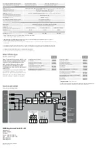
Netzausfallüberbrückung bei 400 / 500 Vac
Mains drop compensation at 400 / 500 Vac
13,2 / 36,8 ms
15,6 / 42,9 ms
Überspannungsschutz
Over voltage protection
durch Varistor im Primärstromkreis
through varistor in primary circuit
Anschlüsse: WAGO Multisteckersystem
Terminals: WAGO multi plug system
WAGO Serie 231, max 2,5 mm²
WAGO series 231, max. 2.5 mm²
Ausgangsdaten
Output
Ausgangsnennspannung
Rated output voltage
24 Vdc
Ausgangsspannungsbereich
Rated output voltage range
22,8 – 28,8 Vdc
Ausgangsnennstrom bei 24 Vdc
Rated output current at 24 Vdc
10 Adc
20 Adc
40 Adc
Power Boost **
(bei Betrieb von 3 Eingangsphasen)
Power Boost
(if operation with 3 input phases)**
20 Adc / 4 s (15 Adc / 16 s)
40 Adc / 4 s (30 Adc / 16 s)
60 Adc / 4 s (50 Adc / 16 s)
Dauerhaft zu entnehmender Ausgangsstrom
bei Betrieb von nur 2 Eingangsphasen
Continuous output current allowed if only
operated with 2 input phases
10 Adc
20 Adc
25 Adc
Power Boost bei Betrieb von nur
2 Eingangsphasen
Power Boost if only operated with
2 input phases
20 Adc / 4 s
25 Adc / 4 s
40 Adc / 4 s
Top Boost
Top Boost
70 Adc
80 Adc
100 Adc
Strombegrenzung
Current limitation
typ. 1,1 x I
nenn
typ. 1.1 x Irated
Wirkungsgrad
Efficiency
typ. 91,7 %
typ. 92,9 %
typ. 93,6 %
max. Verlustleistung Leerlauf / Nennlast
max. Power loss idling / nominal load
7,8 / 19,9 W
8,3 / 34,1 W
7,0 / 61,5 W
Restwelligkeit
Residual ripple
typ. 70 mVpp
Parallelschaltbarkeit
Parallel operation
ja, zur Leistungserhöhung
yes, for increased power
Technische Daten
Technical details
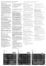
001
979
log
kh
h
003
SET
log
time
kh
SET
297
log
time
h
003
297
log
time
kh
h
STO
003
297
log
time
kh
h
003
297
time
kh
h
SET
I.Co
Iout
005
I.t
Iout
s
STO
I.Co
STO
I.Fu
FU
I.Co
Iout
Uo.L
22,5
Ui.L
375
SET
377
Ui.L
STO
Ui
402
Uo.H
26,7
F r
50
Hz
F L
50
Hz
Ui.H
430
SET
420
Ui.H
STO
Err
!!!
Err
!$!
Io.H
27.5
23.9
Uout
Vdc
9,76
Iout
Adc
25,5
Uout
Vdc
SET
STO
Uo
2
3
4
5
6
7
8
9
10
11
12
13
14
15
SET
I.Fu
23.9
Uout
Vdc
9,76
Iout
Adc
1
Segment blinkt
Segment blinks
Uo
Ausgangsspannung
output voltage
STO
Einstellungen gespeichert
store
SET
Einstellungen vornehmen
setting
FU
Überstrommodus
overload current behaviour
I.Co
Konstantstrommodus
constant current mode
I.Fu
Fuse mode
fuse mode
I.t
Konstantstromzeit
constant current time
Uo.H
max. Ausgangsspannung
max. output voltage
Uo.L
min. Ausgangsspannung
min. output voltage
Ui
Eingangsspannung
input voltage
Ui.L
min. Eingangsspannung
min. input voltage
Ui.H
max. Eingangsspannung
max. input voltage
F
Frequenz
frequency
r
Drehfeldrichtung rechts
rotary field direction is cw
L
Drehfeldrichtung links
rotary field direction is ccw
I.Hi
max. Ausgangsstrom
max. output current
Err
Fehlermanager
fault manager


