WAGO I/O SYSTEM 750 XTR
Process Image 37
750-633/040-000 Up/Down Counter Ex i XTR
Manual
Version 1.1.0
3.
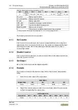
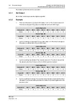
Wait for feedback from the Up/Down Counter in the status byte, bit 5
(counter set).
Status Byte S0
Input bit
Bit 7 Bit 6 Bit 5 Bit 4 Bit 3 Bit 2 Bit 1 Bit 0
Value
X
X
1
X
X
X
X
X
4.
Clear bit 5 (set counter) in the control byte to complete the handshake.
Control Byte C0
Output bit
Bit 7 Bit 6 Bit 5 Bit 4 Bit 3 Bit 2 Bit 1 Bit 0
Value
0
X
0
X
X
X
X
X
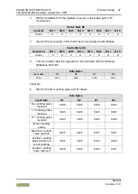
5.
The set counter value then appears in the input data with the following
databases D0 to D3.
Data Bytes
Input data
D3
D2
D1
D0
Value
0x00
0x00
0x00
0x64
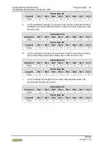
Count up:
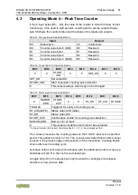
6.
Wait for the first counting pulse and for others.
Data Bytes
Input data
D3
D2
D1
D0
No counting pulse
received
0x00
0x00
0x00
0x64
1
st
counting pulse
received
0x00
0x00
0x00
0x65
2
nd
counting pulse
received
0x00
0x00
0x00
0x66
More counting
pulses
...
...
...
...
Maximum counter
value reached
0xFF
0xFF
0xFF
0xFF
Another counting
pulse results in a
count overflow
0x00
0x00
0x00
0x00
Another counting
pulse received
0x00
0x00
0x00
0x01


