WAGO-I/O-System 750
Device Description
49
750-370 PROFINET IO Fieldbus Coupler
Manual
Version 2.0.0
Pos: 32 /All e Seri en (Allgemei ne Module)/Ü berschriften für alle Serien/Gerätebeschreibung/Anzeigeel emente - Überschrift 2 @ 4\mod_1240984390875_21.docx @ 31964 @ 2 @ 1
4.4
Display Elements
Pos: 33.1 /Serie 750 (WAGO-I/O-SYST EM)/Ger ätebeschrei bung/Anzeigeelemente/Fel dbuskoppl er/-contr oller/Legende/Anzeigeelemente - Ei nlei tung (Koppler) @ 4\mod_1239098122920_21.docx @ 30150 @ @ 1
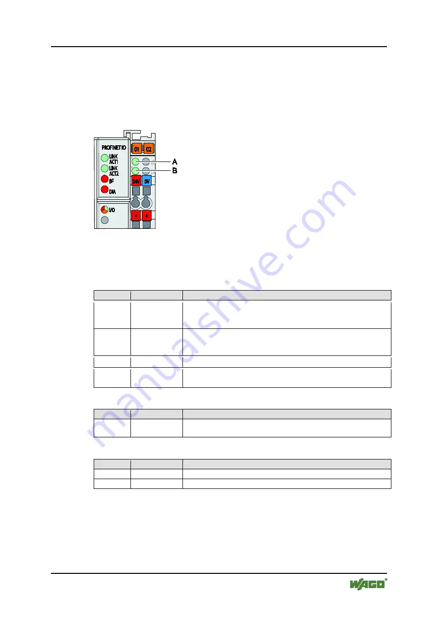
The operating condition of the fieldbus coupler or the node is displayed with the
help of illuminated indicators in the form of light-emitting diodes (LEDs).
The LED information is routed to the top of the case by light guides. In some
cases, the LEDs are multi-colored (red, green or orange).
Pos: 33.2 /Serie 750 (WAGO-I/O-SYST EM)/Ger ätebeschrei bung/Anzeigeelemente/Fel dbuskoppl er/-contr oller/Bilder/Anzeigeelemente 750- 0370 - Bild @ 22\mod_1429522520396_21.docx @ 180576 @ @ 1
Figure 24: Display Elements
Pos: 33.3 /Serie 750 (WAGO-I/O-SYST EM)/Ger ätebeschrei bung/Anzeigeelemente/Fel dbuskoppl er/-contr oller/Legende/Anzeigeelemente - Ei nlei tung und T abellenüberschrift F eldbusstatus ( Standard) @ 4\mod_1240920871636_21.docx @ 31795 @ @ 1
+
For the diagnostics of the different domains fieldbus, node and supply voltage, the
LEDs can be divided into three groups:
Table 15: Display Elements Fieldbus Status
LED
Color
Meaning
Pos: 33.4 /Serie 750 (WAGO-I/O-SYST EM)/Ger ätebeschrei bung/Anzeigeelemente/Fel dbuskoppl er/-contr oller/Legende/Anzeigeelemente - F eldbusstatus PROFIN ET- basi ert, spezifischer T abellenteil 'LIN K ACT 1,2' @ 23\mod_1439199059516_21.docx @ 187718 @ @ 1
LINK
ACT 1
green
indicates a connection to the physical network at port 1 and flashes
with a frequency of 2 Hz for a period of 3 seconds when the fieldbus
coupler is requested to the participant flash test by the DCP protocol.
LINK
ACT 2
green
indicates a connection to the physical network at port 2 and flashes
with a frequency of 2 Hz for a period of 3 seconds when the fieldbus
coupler is requested to the participant flash test by the DCP protocol.
Pos: 33.5 /Serie 750 (WAGO-I/O-SYST EM)/Ger ätebeschrei bung/Anzeigeelemente/Fel dbuskoppl er/-contr oller/Legende/Anzeigeelemente - F eldbusstatus PROFIN ET IO- basi ert, spezifischer T abellenteil 'BF' (rot) @ 22\mod_1429524986891_21.docx @ 180580 @ @ 1
BF
red
indicates whether communication via the PROFINET is functioning
Pos: 33.6 /Serie 750 (WAGO-I/O-SYST EM)/Ger ätebeschrei bung/Anzeigeelemente/Fel dbuskoppl er/-contr oller/Legende/Anzeigeelemente - F eldbusstatus PROFIN ET IO- basi ert, spezifischer T abellenteil 'DIA' ( 370) @ 22\mod_1429525524046_21.docx @ 180598 @ @ 1
DIA
red
indicates the upcoming diagnoses. The signaling is not supported by
all I/O modules or have explicitly be enabled for each channel.
Pos: 33.7 /Serie 750 (WAGO-I/O-SYST EM)/Ger ätebeschrei bung/Anzeigeelemente/Fel dbuskoppl er/-contr oller/Legende/Anzeigeelemente - Knotenstatus Tabellenüberschrift und 'I/O' (PR OFIBUS, PR OFIN ET) @ 19\mod_1403014582066_21.docx @ 156108 @ @ 1
+
Table 16: Display Elements Node Status
LED
Color
Meaning
I/O
red/green/
orange
indicates a state of start-up (orange) as well as the operation of the
node (green) and signals via a blink code (red) faults encountered.
Pos: 33.8 /Serie 750 (WAGO-I/O-SYST EM)/Ger ätebeschrei bung/Anzeigeelemente/Fel dbuskoppl er/-contr oller/Legende/Anzeigeelemente - Versorgungsspannungsstatus T abell enüberschrift und 'A', 'B' @ 5\mod_1253265337073_21.docx @ 41846 @ @ 1
+
Table 17: Display Elements Supply Voltage
LED
Color
Meaning
A
green
indicates the status of the operating voltage – system
B
green
indicates the status of the operating voltage – power jumper contacts
Pos: 33.9 /Serie 750 (WAGO-I/O-SYST EM)/Ger ätebeschrei bung/Anzeigeelemente/Fel dbuskoppl er/-contr oller/Legende/Infor mation: Infor mationen zu der LED- Signalisi erung @ 4\mod_1239098329547_21.docx @ 30154 @ @ 1


