background image


78

1SP4QSBZr

I

1VMJ[JBEFMMBQQBSFDDIJP NFTTBGVPSJTFSWJ[JP

&MJNJOB[JPOFEJBOPNBMJF

Tipo di anomalia


" -BQQBSFDDIJPOPOTJNFUUFJO

funzione

# -BQQBSFDDIJPOPOBTQJSB

$ -BQQBSFDDIJPBTQJSBNBMB

pressione non aumenta

Possibile causa


 .BODBO[BEJUFOTJPOFFMFUUSJDB


2.  Regolazione su pressione 

JOTVîDJFOUF

 *OUFSSVUUPSF0/0''HVBTUP

 7BMWPMBEJTñBUPSFHPMBUBTV413": 

p


spruzzatura).


2. 

Il filtro sporge oltre il pelo libero del 

MJRVJEPFEBTQJSBBSJB


3.  Filtro intasato.


4. 

Tubo flessibile di aspirazione/

Tubo di aspirazione allentato, cioè 

MBQQBSFDDIJPBTQJSBBSJBQBSBTTJUB

 -VHFMMPÍGPSUFNFOUFVTVSBUP

 6HFMMPUSPQQPHSBOEF


3.  Regolazione su pressione 

JOTVîDJFOUF


4.  Filtro intasato.


5. 

Il materiale di copertura fluisce 
attraverso il tubo flessibile di ritorno 

RVBOEPMBWBMWPMBEJTñBUPTJUSPWBJO

QPTJ[JPOF413": 

p

 spruzzatura).


6.  Guarnizioni incollate o usurate.


7.  Sfere delle valvole usurate.


8.  Sedi delle valvole usurate.

Misura per eliminare l’anomalia


1.  Controllare la tensione di alimentazione.


2.  Ruotare la manopola di regolazione della pressione  su 

valori maggiori.


3.  Sostituire.

 1PSUBSFMBWBMWPMBEJTñBUPTV13*.& 

k

 circolazione).


2.  Rifornire con materiale di copertura.


3. 

Pulire o sostituire il filtro.


4.  Pulire i raccordi. Serrare il tubo di aspirazione.


1.  Sostituire.

 4DFHMJFSFVOVHFMMPQJÜQJDDPMPWFEJMBUBCFMMBEFHMJVHFMMJ

a pag. 84.


3.  Ruotare la manopola di regolazione della pressione su un 

valore maggiore.


4.  Pulire o sostituire il filtro.


5.  Smontare la valvola di sfiato e pulirla o sostituirla. 


6.  Smontare le guarnizioni e pulirle o sostituirle.


7.  Smontare e sostituire le sfere delle valvole.


8.  Smontare e sostituire le sedi delle valvole.

9. 

Eliminazione di anomalie

8.3 

Pulizia dell’aerografo Airless

  -BWBSFMBFSPHSBGP"JSMFTTDPOVOEFUFSHFOUFBEBUUPBCBTTB

pressione di esercizio.

  1VMJSFBDDVSBUBNFOUFMVHFMMPDPOVOEFUFSHFOUFBEBUUP

assicurandosi di eliminare tutti i residui di materiale di 

copertura.

  1VMJSFBDDVSBUBNFOUFMFTUFSOPEFMMBFSPHSBGP"JSMFTT

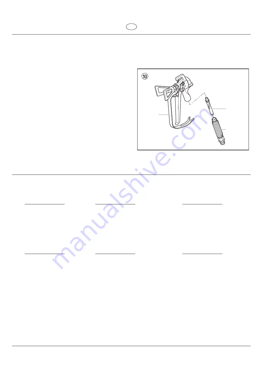
Filtro innestabile dell’aerografo Airless

4NPOUBHHJP ñH


1. 

Tirare con forza in avanti la staffa di protezione (1).

  4WJUBSFMJNQVHOBUVSB EBMMBMMPHHJBNFOUPEFMMBFSPHSBGP

Estrarre il filtro innestabile (3).


3.  Sostituire un filtro innestabile intasato o difettoso.

Montaggio

  *OTFSJSFJMñMUSPJOOFTUBCJMF DPOJMDPOPQJÜMVOHP

OFMMBMMPHHJBNFOUPEFMMBFSPHSBGP

  "WWJUBSFMJNQVHOBUVSB OFMMBMMPHHJBNFOUPEFMMBFSPHSBGPF

serrare.


3. 

Innestare in posizione la staffa di protezione (1).

  W

arning:

keep clear
     of ti

p

         250 bar
max.3600 ps

i

3

2

1

Summary of Contents for ProSpray 3.29

Page 1: ...l p 22 Mode d emploi p 44 Istruzioni per l uso p 66 Airless Hochdruck Spritzgerät Airless high pressure spraying unit Groupe de projection à haute pression Impianto per la verniciatura a spruzzo ad alta pressione Airless Models 0558005 0558006 0558037 0558038 Original operating manual PS 3 29 14 ...

Page 2: ... schnellen fachkundigen Behandlung Informieren Sie den Arzt über den verwendeten Beschichtungsstoff oder das Lösemittel Vor jeder Inbetriebnahme sind gemäß Betriebsanleitung folgende Punkte zu beachten 1 Fehlerhafte Geräte dürfen nicht benutzt werden 2 Wagner Spritzpistole sichern mit Sicherungshebel am Abzugsbügel 3 Erdung sicherstellen 4 Zulässigen Betriebsdruck von Hochdruckschlauch und Spritzp...

Page 3: ...8 4 7 Digital Electronic Spray Control DESC 8 5 Spritztechnik 10 6 Handhabung des Hochdruckschlauches 10 7 Arbeitsunterbrechung 10 8 Gerätereinigung Außerbetriebnahme 11 8 1 Gerätereinigung von außen 11 8 2 Hochdruckfilter reinigen 11 8 3 Reinigung der Airless Spritzpistole 12 Seite 9 Hilfe bei Störungen 12 8BSUVOH 14 10 1 Allgemeine Wartung 14 10 2 Hochdruckschlauch 14 3FQBSBUVSFO BN FSÅU 14 11 1...

Page 4: ... SVDL BT 7FOUJM 13 413 7PSGÛMM 4QSÛIWFOUJM C X das Druckentlastungsventil müssen in ihren Sollpositionen stehen um den Systemdruck zu entspannen r 45 54 EFO ÛTFOTDIVU BVGTFU FO XFOO 4QSJU BSCFJUFO durchgeführt werden Der Düsenschutz stellt einen gewissen Schutz dar ist aber vor allem als Warnvorrichtung gedacht r 45 54 EJF 4QSJU EÛTF FOUGFSOFO CFWPS EBT 4ZTUFN HFSFJOJHU oder gespült wird r 4 FJOF ...

Page 5: ...tung einhalten r FJ FUÅUJHVOH EFT VTMÕTFST JFIU EJF 4QSJU QJTUPMF VS 4FJUF Diese Kraftwirkung der Spritzpistole ist besonders stark wenn die Düse entfernt und bei der Pumpe hoher Druck eingestellt wurde Bei der Reinigung mit abgeschraubter Düse daher den Druckreglerknopf auf den niedrigsten Druck einstellen r VS WPN FSTUFMMFS VHFMBTTFOF 5FJMF WFSXFOEFO FJ Verwendung von Teilen die nicht die techni...

Page 6: ...ine Kolbenpumpe saugt den Beschichtungsstoff an und fördert JIO VOUFS SVDL VS ÛTF FJ FJOFN SVDL CJT NBY CBS 1B EVSDI EJF ÛTF HFQSFTTU FSTUÅVCU EFS FTDIJDIUVOHTTUPí Dieser hohe Druck bewirkt eine mikrofeine Zerstäubung des Beschichtungsstoffes Da in diesem System keine Luft verwendet wird bezeichnet man dieses Verfahren als AIRLESS Verfahren luftlos Diese Art zu spritzen bringt die Vorteile von fei...

Page 7: ...syGlide verhindert erhöhten Verschleiß der Packungen 4 Ölstandsanzeige 5 Eimerhaken 6 Knopf für Ölzufuhr 7 Ansaugschlauch 8 Rücklaufschlauch 9 Hoher Wagen 10 Entlastungsventil FCFMTUFMMVOH TFOLSFDIU m 13 k Zirkulation FCFMTUFMMVOH XBBHSFDIU m 413 p Spritzen 11 Digital Electronic Spray Control DESC 12 Bedienfeld 13 Druckregler 0 m 0 64 4DIBMUFS SLMÅSVOHTCJME 1SP4QSBZ ...

Page 8: ...ausziehen Handgriff einfahren Druckknöpfe 2 an den Holmen eindrücken dann Handgriff einfahren 2 1 2 3 7 Transport im Fahrzeug Gerät mit geeignetem Befestigungsmittel sichern 4 Inbetriebnahme PDIESVDLTDIMBVDI 4QSJU QJTUPMF VOE Trennöl 1 An den Beschichtungsstoff Ausgang Abb 3 Pos 1 den Hochdruckschlauch 2 schrauben 2 Spritzpistole 3 mit ausgewählter Düse an den Hochdruckschlauch anschrauben 3 Überw...

Page 9: ...et r BT 4QSJU HFSÅU BSCFJUFU NJU EFS SJDIUJHFO SVDLFJOTUFMMVOH GÛS EBT 4QSJU FO NJU M VOE BUFYGBSCFO r BT 4QSJU HFSÅU BSCFJUFU EBOO NJU PQUJNBMFS FJTUVOH CFJ hoher Druckeinstellung r 8FOO CFJ EFS SVDLFJOTUFMMVOH EJF SVDLBO FJHF TUÅOEJH gelb leuchtet aber nach der Druckeinstellung ständig grün leuchten sollte liegen folgende Fehler vor a Verschlissene Düse FJN 7FSTQSÛIFO WPO BUFYGBSCF oder beim Ver...

Page 10: ...en die Bedienung des Spritzgerätes überwachen und anpassen kann MPa SOLL 23 0 MPa IST 22 5 Display Funktionstasten i Der Druckregler hat Vorrang vor den Einstellungen des Digital Electronic Spray Control DESC Bei jeder Drehung des Druckreglers ändert sich der Druck des Spritzgeräts entsprechend Funktionstasten JF VOLUJPOTUBTUFO IBCFO EJF VNNFSO CJT FEFS Funktionstaste ist außerdem eine Sonderfunkt...

Page 11: ...rm Wartung erforderlich an Die Pumpe bleibt jedoch auch weiterhin CFUSJFCTGÅIJH 6N VN BVQUCJMETDIJSN VSÛDLHFMBOHFO ESÛDLFO 4JF EJF 5BTUF 4P LÕOOFO i8BSUVOH JOu VOE i FUSJFCTTUVOEFOu EJF auf dem Wartungsbildschirm angezeigt werden wieder auf 0 gesetzt werden Menüfenster Security Code Sicherheitscode SICHERHEITSCODE AENDERN 2 MENU 1 N FOÛGFOTUFS 4FDVSJUZ PEF 4JDIFSIFJUTDPEF LBOO EFS FOVU FS FJOFO vi...

Page 12: ...uckschlauch sofort ersetzen Niemals defekten Hochdruckschlauch selbst reparieren Der Hochdruckschlauch ist sorgsam zu behandeln Scharfes Biegen oder Knicken vermeiden kleinster Biegeradius etwa 20 cm Hochdruckschlauch nicht überfahren sowie vor scharfen Gegenständen und Kanten schützen JFNBMT BN PDIESVDLTDIMBVDI JFIFO VN EBT FSÅU V CFXFHFO Darauf achten dass der Hochdruckschlauch sich nicht verdre...

Page 13: ... zur Reinigung OUMBTUVOHTWFOUJM ÕíOFO 7FOUJMTUFMMVOH 13 k Zirkulation FFJHOFUFT 3FJOJHVOHTNJUUFM FJOJHF JOVUFO JN SFJTMBVG pumpen OUMBTUVOHTWFOUJM TDIMJF FO 7FOUJMTUFMMVOH 413 p Spritzen 10 Abzugsbügel an der Spritzpistole ziehen 11 Restliches Reinigungsmittel in einen offenen Behälter pumpen bis das Gerät leer ist FSÅU BVTTDIBMUFO 0 64 FSÅUFSFJOJHVOH WPO BV FO Zuerst Netzstecker aus der Steckdose...

Page 14: ... Ventilsitze verschlissen Maßnahme zur Behebung der Störung 1 Spannungsversorgung prüfen 2 Druckregler höher drehen 3 Austauschen OUMBTUVOHTWFOUJM BVG 13 k Zirkulation stellen 2 Beschichtungsstoff nachfüllen 3 Filter reinigen oder austauschen 4 Anschlussstellen reinigen Ansaugrohr anziehen 1 Austauschen 2 Wahl einer kleineren Düse siehe Düsentabelle Seite 18 SFIFO 4JF EFO SVDLSFHMFS JN 6IS FJHFSTJ...

Page 15: ...reduzieren Trennen Sie das Spritzgerät vor Wartungsarbeiten stets vom Netz Menüfenster Check Transducer Sensor überprüfen MESSFUEHLER PRUEFEN BT FOÛGFOTUFS IFDL 5SBOTEVDFS 4FOTPS ÛCFSQSÛGFO FSTDIFJOU XFOO EFS Sensor defekt ist oder sich gelöst hat Bringen Sie das Spritzgerät zur Reparatur in eine Vertragswerkstatt von Wagner Menüfenster Check Motor Motor überprüfen MOTOR PRUEFEN BT FOÛGFOTUFS IFDL...

Page 16: ...er Schrauben im Frontdeckel entfernen Frontdeckel abnehmen Quetschgefahr nicht mit den Fingern oder Werkzeug zwischen die sich bewegenden Teile fassen 2 Stellen Sie den Druckregler auf den geringsten Druck ein Der 4 JMETDIJSN TPMMUF 703 BO FJHFO FUÅUJHFO 4JF EJF 5BTUF BVG EFN 4 FEJFOGFME FS JMETDIJSN 4 0 64 FSTDIFJOU SFIFO 4JF EFO SVDLSFHMFS MBOHTBN JO 6IS FJHFSTJOO VN EFO Druck zu erhöhen Die Kur...

Page 17: ...prüfen wenn notwendig Teile austauschen Verschlissener Auslassventilsitz 20 falls er auf einer Seite unbenützt ist umgedreht einbauen POUBHF JO VNHFLFISUFS 3FJIFOGPMHF EVSDIGÛISFO 0 3JOH NJU BTDIJOFOGFUU FJOTUSFJDIFO VOE BVG SJDIUJHFO 4JU JN unteren Gehäuse 10 achten 11 15 16 17 18 19 20 14 12 13 10 1BDLVOHFO 1 Einlassventilgehäuse entsprechend den Schritten unter Kapitel 11 2 Seite 14 ausbauen 2 ...

Page 18: ...22 Arretiermutter 5 bis zur Anlage am oberen Gehäuse 6 aufschrauben FXJOEF EFT PCFSFO FIÅVTFT NJU BTDIJOFOGFUU einstreichen 0CFSFT FIÅVTF TPXFJU JO EBT FUSJFCFHFIÅVTF einschrauben bis die Arretiermutter 5 zur Anlage kommt und der Anschluss für den Verbindungsschlauch nach hinten zeigt 25 Arretiermutter 5 mit leichten Hammerschlägen anziehen 26 Führungsring 11 in das untere Gehäuse Abb 13 Pos 10 ei...

Page 19: ...einsatzbereit zu halten OUMBTUVOHTWFOUJM ÕíOFO 7FOUJMTUFMMVOH 13 k Zirkulation 2 Gerät ausschalten 3 Düse von der Spritzpistole demontieren 4 Düse in ein entsprechendes Reinigungsmittel legen bis alle Beschichtungsstoffreste aufgelöst sind 5 Wenn Druckluft vorhanden ist Düse ausblasen JU FJOFN TQJU FO IÕM FSOFO 4UBC BIOTUPDIFS FWFOUVFMMF 3FTUF FOUGFSOFO 7 Die Düse unter Zuhilfenahme eines Vergröße...

Page 20: ...3 0 013 0 33 100 120 150 190 225 270 330 Rot Rot Rot Rot Rot Rot Rot 0553113 0553213 0553313 0553413 0553513 0553613 0553813 Füller Rostschutzfarben 115 215 315 415 515 615 715 815 0 015 0 38 0 015 0 38 0 015 0 38 0 015 0 38 0 015 0 38 0 015 0 38 0 015 0 38 0 015 0 38 100 120 150 190 225 270 300 330 Gelb Gelb Gelb Gelb Gelb Gelb Gelb Gelb 0553115 0553215 0553315 0553415 0553515 0553615 0553715 055...

Page 21: ...eiß Weiß Weiß Weiß Weiß Weiß Weiß Weiß Weiß Weiß Weiß Weiß Weiß Weiß Weiß Weiß Weiß Weiß Weiß Weiß Weiß Weiß Weiß Weiß Weiß Weiß Weiß Weiß Weiß Weiß Weiß Weiß Weiß Weiß Weiß Weiß 0553225 0553325 0553425 0553525 0553625 0553725 0553825 0553227 0553327 0553427 0553527 0553627 0553827 0553229 0553329 0553429 0553529 0553629 0553231 0553331 0553431 0553531 0553631 0553731 0553831 0553233 0553333 05534...

Page 22: ...FMTUBIMTDIMBVDI i N 4QSBZQBDL CFTUFIFOE BVT BTJTFJOIFJU JSMFTT 1JTUPMF 14 i JOLM 5SBEF 5JQ ÛTFOIBMUFS FX und Trade Tip 2 Düse Fine Finish 410 2311660 2311853 TempSpray H 226 optimal für Dispersionen hochviskose Materialien BTJTFJOIFJU i JOLM 4DIMBVDIUSPNNFM FJ TDIMBVDI N 4DIMBVDIQFJUTDIF i N 4QSBZQBDL CFTUFIFOE BVT BTJTFJOIFJU JSMFTT 1JTUPMF 14 i JOLM 5SBEF 5JQ ÛTFOIBMUFS FX und Trade Tip 2 Düse 4...

Page 23: ...OFOCFSFJDI möglich r FJOF 3FJOJHVOH CFJ SCFJUTVOUFSCSFDIVOHFO PEFS 0SUTXFDITFM OÕUJH EB BSCF JO EFS 1VNQF OJDIU BOUSPDLOFO C X BVTMBVGFO LBOO r 7FSCFTTFSUF POTFSWJFSVOH r JOGBDITUF POUBHF Geeignet für folgende Modelle Membranpumpen Kolbenpumpen SF 21 SF 23 SF 27 SF 31 SF 7000 Finish 270 370 FTQSBZ FDP FTQSBZ PS 24 PS 26 PS 30 PS 34 PS 3 25 PS 3 29 PS 3 31 PS 3 34 i MFJDI NJUCFTUFMMFO BTZ MFBO 3FJO...

Page 24: ...ment Inform the doctor about the coating material or solvent used The operating instructions state that the following points must always be observed before starting up 1 Faulty units must not be used 4FDVSF 8 3 TQSBZ HVO VTJOH UIF TBGFUZ DBUDI PO UIF USJHHFS 3 Ensure that the unit is properly earthed 4 Check allowable operating pressure of high pressure hose and spray gun 5 Check all connections f...

Page 25: ...tronic Spray Control DESC 30 5 Spraying technique 32 6 Handling the high pressure hose 32 7 Interruption of work 32 8 Cleaning the unit shutting down 33 8 1 Cleaning unit from outside 33 8 2 Cleaning the high pressure filter 33 8 3 Cleaning Airless spray gun 34 Page 9 Remedy in case of faults 34 4FSWJDJOH 36 10 1 General servicing 36 10 2 High pressure hose 36 3FQBJST BU UIF VOJU 36 11 1 Relief va...

Page 26: ...S BCPWF UIF NBYJNVN operating pressure range of the sprayer This includes spray UJQT HVOT FYUFOTJPOT BOE IPTF HAZARD HIGH PRESSURE HOSE The paint hose can develop leaks from wear kinking and abuse A leak can inject material into the skin Inspect the hose before each use PREVENTION r JHI QSFTTVSF IPTFT NVTU CF DIFDLFE UIPSPVHIMZ CFGPSF UIFZ are used r 3FQMBDF BOZ EBNBHFE IJHI QSFTTVSF IPTF JNNFEJBU...

Page 27: ...JBM NBOVGBDUVSFS T JOTUSVDUJPOT GPS safe handling of paint and solvents r MFBO VQ BMM NBUFSJBM BOE TPMWFOU TQJMMT JNNFEJBUFMZ UP QSFWFOU slip hazard r 8FBS FBS QSPUFDUJPO 5IJT VOJU DBO QSPEVDF OPJTF MFWFMT BCPWF 85 dB A r FWFS MFBWF UIJT FRVJQNFOU VOBUUFOEFE FFQ BXBZ GSPN children or anyone not familiar with the operation of airless FRVJQNFOU r FWJDF XFJHIT JO FYDFTT PG LH 5ISFF QFSTPO MJGU JT SFR...

Page 28: ... suction and conveys it UP UIF UJQ 1SFTTFE UISPVHI UIF UJQ BU B QSFTTVSF PG VQ UP B NBYJNVN PG CBS 1B UIF DPBUJOH NBUFSJBM JT BUPNJTFE 5IJT IJHI pressure has the effect of micro fine atomisation of the coating material As no air is used in this process it is described as an AIRLESS process This method of spraying has the advantages of finest atomisation cloudless operation and a smooth bubble free...

Page 29: ...Z MJEF BTZ MJEF QSFWFOUT increased wear of the packings 0JM MFWFM HBVHF 5 Pail hook 0JM CVUUPO 7 Suction tube 8 Return hose 9 Cart 10 Relief valve FWFS QPTJUJPO WFSUJDBM m 13 k circulation FWFS QPTJUJPO IPSJ POUBM m 413 p 11 Digital Electronic Spray Control DESC 12 Control panel indicators 13 Pressure control knob 0 0 TXJUDI YQMBOBUPSZ EJBHSBN 1SP4QSBZ ...

Page 30: ...the unit Pull out the handle Fig 2 Item 1 until it will come no further Insert the handle push the buttons 2 on the spars and then push in the handle 2 1 2 3 7 Transportation in vehicle Secure the unit with a suitable fastening 4 Starting operation JHI QSFTTVSF IPTF TQSBZ HVO BOE TFQBSBUJOH oil 1 Screw the high pressure hose 2 to the coating material outlet Fig 3 Item 1 2 Screw the spray gun 3 wit...

Page 31: ...FTTVSF TFUUJOH GPS TQSBZJOH PJM CBTFE BOE MBUFY IPVTF QBJOUT r 5IF TQSBZFS JT PQFSBUJOH BU QFBL QFSGPSNBODF BU B IJHI pressure setting r G UIF QSFTTVSF JOEJDBUPS HPFT UP TPMJE ZFMMPX XIFO UIF pressure is set so that it starts at solid green it indicates one of the following a Tip Wear Indicator XIFO TQSBZJOH XJUI MBUFY PS BU IJHI pressure the solid yellow appears This means the tip is worn and nee...

Page 32: ...play shows various menu screens that allow the user to customize and monitor sprayer operation using the function keys SET MPa 23 0 ACTUAL MPa 22 5 Display Function Keys i The pressure control knob overrides the Digital Electronic Spray Control DESC settings Anytime the pressure control knob is turned the sprayer pressure will change accordingly Function Keys The function keys are numbered 1 4 Eac...

Page 33: ...set the Service and Run Hours displayed on the Service Screen back to 0 Security Code Screen SECURITY CODE CHANGE 2 MENU 1 The Security Code screen allows the user to set a four digit security code to prevent unauthorized use of the sprayer If a security code has been set the control system display will ask for the code at startup If the correct DPEF JT FOUFSFE UIF EJTQMBZ XJMM TIPX UIF BJO 4DSFFO...

Page 34: ...pair defective high pressure hoses yourself The high pressure hose is to be handled with care Avoid sharp bends and folds the smallest bending radius is about 20 cm Do not drive over the high pressure hose Protect against sharp objects and edges FWFS QVMM PO UIF IJHI QSFTTVSF IPTF UP NPWF UIF EFWJDF BLF TVSF UIBU UIF IJHI QSFTTVSF IPTF DBOOPU UXJTU 5IJT DBO CF avoided by using a Wagner spray gun w...

Page 35: ...BMWF QPTJUJPO 13 k circulation 8 Pump a suitable cleaning agent in the circuit for a few minutes MPTF UIF SFMJFG WBMWF WBMWF QPTJUJPO 413 p spray 10 Pull the trigger of the spray gun 11 Pump the remaining cleaning agent into an open container until the unit is empty 4XJUDI UIF VOJU 0 MFBOJOH VOJU GSPN PVUTJEF First of all pull out mains plug from socket Attention Danger of short circult through pa...

Page 36: ...icky or worn 7 Valve balls worn 8 Valve seats worn Measures for eliminating the malfunction 1 Check voltage supply 2 Turn up pressure control knob 3 Replace 4FU SFMJFG WBMWF UP 13 k circulation 2 Refill the coating material 3 Clean or replace the filter 4 Clean connecting points Tighten suction tube 1 Replace 2 For selection of a smaller tip see Tip table on Page 40 3 Turn pressure control knob cl...

Page 37: ... any pressure remaining in the system valve position PRIME k Additionally follow all other warnings to reduce the risk of an injection injury injury from moving parts or electric shock Always unplug the sprayer before servicing Check Transducer Screen CHECK TRANSDUCER The Check Transducer screen appears when the transducer has become disconnected or is defective Take the sprayer to a Wagner author...

Page 38: ...WBMWF 1 Remove the four screws in the front cover and then remove the front cover Danger of crushing do not reach with the fingers or tool between the moving parts 2 Turn the pressure control knob to minimum pressure The 4 TDSFFO TIPVME TBZ i13 u 1SFTT UIF LFZ PO UIF 4 DPOUSPM QBOFM 5IF i 3 1 0 u TDSFFO XJMM OPX BQQFBS 4 Slowly turn the pressure control knob clockwise to increase the pressure The ...

Page 39: ...0 14 12 13 10 1BDLJOHT 1 Remove inlet valve housing in accordance with the steps in Chapter 11 2 Page 36 2 It is not necessary to remove the outlet valve 3 Loosen lock nut Fig 14 Item 5 counterclockwise with light blows from a hammer 6OTDSFX VQQFS IPVTJOH DPVOUFSDMPDLXJTF GSPN UIF HFBS unit housing 5 Clamp upper housing 6 at the wrench surfaces vertically in a vice Attention Do not tighten vice ex...

Page 40: ...f the piston 4 into the T slot 2 on the slider assembly 3 22 Screw lock nut 5 at the upper housing 6 until it touches 23 Lubricate the threading of the upper housing 6 with machine grease Remove upper housing from the vice 24 Screw upper housing 6 into the gear unit housing until the lock nut 5 touches and the connector for the connection hose faces the rear 25 Tighten lock nut 5 with light hammer...

Page 41: ... tip clean and ready for use 1 Turn the relief valve handle fully counterclockwise k Circulation 2 Switch off the gasoline engine 3 Dismount the tip from the spray gun 4 Place tip in an appropriate cleaning agent until all coating material residue is dissolved 5 If there is pressure air blow out tip 6 Remove any residue by means of a sharp wooden rod toothpick 7 Check the tip with the help of a ma...

Page 42: ...red red red red red 0553113 0553213 0553313 0553413 0553513 0553613 0553813 Fillers Rust protection paints 115 215 315 415 515 615 715 815 0 015 0 38 0 015 0 38 0 015 0 38 0 015 0 38 0 015 0 38 0 015 0 38 0 015 0 38 0 015 0 38 100 120 150 190 225 270 300 330 yellow yellow yellow yellow yellow yellow yellow yellow 0553115 0553215 0553315 0553415 0553515 0553615 0553715 0553815 Rust protection paint...

Page 43: ...te white white white white white white white white white white white white white white white white white white white white white white white white white white white white white white 0553225 0553325 0553425 0553525 0553625 0553725 0553825 0553227 0553327 0553427 0553527 0553627 0553827 0553229 0553329 0553429 0553529 0553629 0553231 0553331 0553431 0553531 0553631 0553731 0553831 0553233 0553333 0...

Page 44: ...S KPCT BTJD VOJU i JODM TUBJOMFTT TUFFM IPTF i N 4QSBZQBDL DPOTJTUJOH PG CBTJD VOJU JSMFTT HVO 14 i JODM 5SBEF 5JQ OP MFS IPMEFS UISFBE BOE Trade Tip 2 Fine Finish 410 2311660 2311853 TempSpray H 226 ideal for dispersions materials with high viscosity BTJD VOJU i JODM PTF SFFM IFBUFE IPTF N IPTF i N 4QSBZQBDL DPOTJTUJOH PG BTJD VOJU JSMFTT HVO 14 i JODM 5SBEF 5JQ OP MFS IPMEFS UISFBE BOE Trade Tip...

Page 45: ...F JOUFSJPS r P DMFBOJOH OFDFTTBSZ EVSJOH XPSL TUPQQBHF PS DIBOHF PG MPDBUJPO CFDBVTF UIF QBJOU JO UIF QVNQ DBOOPU ESZ PVU PS MFBL r FUUFS QSPUFDUJPO r 4JNQMF BTTFNCMZ Suitable for the following models Diaphragm Pumps Double stroke piston pumps SF 21 SF 23 SF 27 SF 31 SF 7000 Finish 270 370 FTQSBZ FDP FTQSBZ PS 24 PS 26 PS 30 PS 34 PS 3 25 PS 3 29 PS 3 31 PS 3 34 i 0SEFS UIJT BU UIF TBNF UJNF BTZ M...

Page 46: ...ecin Renseignez le médecin sur la nature de la peinture ou du solvant utilisés Avant toute mise en service respecter les points suivants conformément aux instructions de service F KBNBJT VUJMJTFS VO ÊRVJQFNFOU EÊGFDUVFVY 7FSSPVJMMFS MF QJTUPMFU 8BHOFS QBS MF MFWJFS EF TÊDVSJUÊ Æ MB HÄDIFUUF TTVSFS MB NJTF Æ MB UFSSF DPSSFDUF 7ÊSJñFS FU SFTQFDUFS MFT QSFTTJPOT BENJTTJCMFT QPVS MF óFYJCMF FU MF pist...

Page 47: ...ronic Spray Control DESC 52 5 Technique de projection 54 BOJQVMBUJPO EV óFYJCMF Æ IBVUF QSFTTJPO 54 7 Interruptions de travail 54 8 Nettoyage du groupe mise hors service 55 FUUPZBHF FYUÊSJFVS EV HSPVQF 55 FUUPZBHF EV ñMUSF IBVUF QSFTTJPO 55 FUUPZBHF EV QJTUPMFU JSMFTT 56 Page 9 Dépannage 56 OUSFUJFO 58 OUSFUJFO HÊOÊSBM 58 MFYJCMF Æ IBVUF QSFTTJPO 58 3ÊQBSBUJPOT EV NBUÊSJFM 58 7BOOF EF EÊDIBSHF 58 ...

Page 48: ...PUFDUJPO EF MB CVTF GPVSOJU VOF DFSUBJOF QSPUFDUJPO NBJT JM T BHJU QSJODJQBMFNFOU E VO TZTUÍNF E BMBSNF r OMFWF 506 0634 MB CVTF EF QVMWÊSJTBUJPO BWBOU EF SJODFS PV de nettoyer le système r VUJMJTF 4 VO QJTUPMFU QVMWÊSJTBUFVS TBOT CMPDBHF EF HÄDIFUUF FU TBOT QSPUFDUJPO EF HÄDIFUUF r 5PVT MFT BDDFTTPJSFT EPJWFOU QPVWPJS USBWBJMMFS Æ MB QSFTTJPO EF USBWBJM NBYJNBMF EV QVMWÊSJTBUFVS PV BV EFTTVT FDJ ...

Page 49: ...FOU MF QJTUPMFU QVMWÊSJTBUFVS F SFDVM EV QJTUPMFU QVMWÊSJTBUFVS FTU QBSUJDVMJÍSFNFOU QVJTTBOU MPSTRVF MB CVTF B ÊUÊ EÊNPOUÊF FU MPSTRVF MB QPNQF TBOT BJS B ÊUÊ SÊHMÊF TVS VOF QSFTTJPO ÊMFWÊF PST EV OFUUPZBHF TBOT CVTF SÊHMF EPOD MF CPVUPO EF contrôle de la pression sur la pression minimale r VUJMJTF RVF EFT QJÍDFT EF SFDIBOHF E PSJHJOF VUJMJTBUFVS BTTVNF UPVT MFT SJTRVFT T JM VUJMJTF EFT QJÍDFT RV...

Page 50: ...F MB CVTF BWFD VOF QSFTTJPO EF NBYJNVN CBS 1B MF QSPEVJU FTU ÊDMBUÊ FO USÍT ñOFT particules UBOU EPOOÊ M BCTFODF E BJS EBOT DF TZTUÍNF JM FTU DPOOV TPVT MF OPN AIRLESS sans air F QSPDÊEÊ EF QSPKFDUJPO DPNQPSUF MFT BWBOUBHFT UFMT RVF QVMWÊSJTBUJPO USÍT ñOF QFV EF CSPVJMMBSE TVSGBDFT MJTTF TBOT CVMMFT part de ces avantages il y a lieu de mentionner la vitesse de travail et MB NBOJBCJMJUÊ 3 2 Fonctio...

Page 51: ...M VTVSF EFT HBSOJUVSFT OEJDBUFVS EF OJWFBV E IVJMF 5 Crochet de seau PVUPO E IVJMF 5VZBV E BTQJSBUJPO 8 Tuyau de retour 9 Chariot 7BOOF EF EÊDIBSHF QPTJUJPO WFSUJDBMF EV MFWJFS 13 k circulation QPTJUPO IPSJ POUBMF EV MFWJFS 413 p projection 11 Digital Electronic Spray Control DESC 12 Voyants du panneau de commandes PVUPO EF SÊHMBHF EF MB QSFTTJPO OUFSSVQUFVS 0 3 0 33 5 MMVTUSBUJPO 1SP4QSBZ 1SP4QSB...

Page 52: ...PSUJS MB QPJHOÊF ñH QPT FO CVUÊF 1PVS SFOUSFS MB QPJHOÊF FOGPODFS MFT CPVUPOT TVS MFT UVCFT EV DIÄTTJT QVJT SFOUSFS MB QPJHOÊF 2 1 2 3 7 Transport par véhicule TTVSFS MF NBUÊSJFM QBS EFT NPZFOT EF ñYBUJPO BQQSPQSJÊT 4 Mise en service MFYJCMF Æ IBVUF QSFTTJPO QJTUPMFU EF projection et huile de balayage 7JTTFS MF óFYJCMF IBVUF QSFTTJPO TVS MB TPSUJF EF QSPEVJU ñH 3 pos 1 7JTTFS MF QJTUPMFU BWFD TB C...

Page 53: ... MB QVMWÊSJTBUJPO EF QFJOUVSFT Æ CBTF E IVJMF FU EF MBUFY QPVS VTBHF EPNFTUJRVF r MF QVMWÊSJTBUFVS GPODUJPOOF Æ QMFJO SÊHJNF Æ VO SÊHMBHF ÊMFWÊ de pression r TJ MF WPZBOU EF QSFTTJPO QBTTF BV KBVOF ñYF RVBOE MB QSFTTJPO FTU SÊHMÊF QPVS RV JM EÊNBSSF BV WFSU ñYF JM JOEJRVF M VO EFT ÊUBUT TVJWBOUT a usure de l embout m QFOEBOU VOF QVMWÊSJTBUJPO BWFD EV MBUFY PV Æ IBVUF QSFTTJPO MF WPZBOU QBTTF BV KB...

Page 54: ...TBUFVS EF QFSTPOOBMJTFS FU EF TVSWFJMMFS MF GPODUJPOOFNFOU EV QVMWÊSJTBUFVS Æ M BJEF EFT UPVDIFT EF GPODUJPOT REG MPa 23 0 MPa ACTUEL 22 5 Écran Touches de fonctions i Le bouton de réglage de pression a la priorité sur les réglages du système numérique Digital Electronic Spray Control DESC À chaque fois qu on tourne le bouton de réglage de pression la pression du pulvérisateur change Touches de fo...

Page 55: ... Æ DIBRVF QSFTTJPO EF touche 2VBOE VOF EVSÊF FTU EÊñOJF FU RVF DF OPNCSF E IFVSFT FTU BUUFJOU M ÊDSBO BîDIF VOF GFOËUSF j 4FSWJDF 3FRVJSFE v OUSFUJFO OÊDFTTBJSF B QPNQF SFTUF PQÊSBUJPOOFMMF 1PVS SFWFOJS Æ MB GFOËUSF QSJODJQBMF BQQVZF TVS MB UPVDIF FMB SFNFU Æ ÊSP MFT EPOOÊFT j 4FSWJDF v FU j 3VO PVST v 53 7 BîDIÊFT EBOT MB GFOËUSF E FOUSFUJFO Security Code Screen Fenêtre de code de sûreté CODE SEC...

Page 56: ...EF SÊQBSFS VO óFYJCMF FOEPNNBHÊ F UVZBV óFYJCMF IBVUF QSFTTJPO EPJU ËUSF USBJUÊ BWFD TPJO M GBVU ÊWJUFS EF USPQ QMJFS MF óFYJCMF MF QMVT QFUJU SBZPO OF EPJU QBT ËUSF JOGÊSJFVS Æ 20 cm 1SPUÊHFS MF óFYJCMF DPOUSF MF QBTTBHF EF WÊIJDVMFT FU ÊWJUFS MF frottement sur des arêtes vives F KBNBJT UJSFS TVS MF óFYJCMF Æ IBVUF QSFTTJPO QPVS EÊQMBDFS MABQQBSFJM BJSF BUUFOUJPO Æ OF QBT UPSESF MF óFYJCMF Æ IBVU...

Page 57: ...JUJPO 13 k circulation 1PNQFS MF QSPEVJU EF OFUUPZBHF QFOEBOU RVFMRVFT NJOVUFT FO DJSDVJU GFSNÊ FSNFS MB WBOOF EF EÊDIBSHF QPTJUJPO 413 p projection 5JSFS MB HÄDIFUUF EV QJTUPMFU 1PNQFS MFT SFTUFT EV QSPEVJU EF OFUUPZBHF EBOT VO SÊDJQJFOU PVWFSU QPVS WJEFS MF NBUÊSJFM SSËUFS MF NBUÊSJFM 0 33 5 FUUPZBHF FYUÊSJFVS EV HSPVQF Tirer d abord la fiche de la prise de secteur Attention Danger de court circ...

Page 58: ...EFT TPVQBQFT VTÊFT 4JÍHFT EFT TPVQBQFT VTÊFT Remède POUSÔMFS M BMJNFOUBUJPO 2 Tourner le bouton pour augmenter la pression 3 Remplacer 5PVSOFS MB WBOOF EF EÊDIBSHF TVS 13 k circulation 2 Ajouter du produit FUUPZFS PV SFNQMBDFS MF ñMUSF FUUPZFS MFT SBDDPSET TFSSFS MF UVCF E BTQJSBUJPO 1 Remplacer 2 Choisir une buse plus petite voir tableau des buses page 62 5PVSOFS MF CPVUPO TVS VO DIJíSF QMVT ÊMFW...

Page 59: ... pulvérisateur avant d en faire l entretien Check Transducer Screen Fenêtre de vérification du transducteur VERIF TRANSDUCT B GFOËUSF j IFDL 5SBOTEVDFS v 7ÊSJñFS MF USBOTEVDUFVS T BîDIF TJ MF USBOTEVDUFVS TF EÊDPOOFDUF PV FTU EÊGFDUVFVY NNFOF MF QVMWÊSJTBUFVS Æ VO DFOUSF UFDIOJRVF BHSÊÊ 8BHOFS QPVS SÊQBSBUJPO Check Motor Screen Fenêtre de vérification du moteur VERIF MOTEUR B GFOËUSF j IFDL PUPS v...

Page 60: ...VWFSDMF GSPOUBM SFUJSFS MF DPVWFSDMF Danger de contusion ne pas mettre les doigts ou un outil entre les parties en mouvement 5PVSOF MF CPVUPO EF DPNNBOEF EF QSFTTJPO KVTRV BV SÊHMBHF NJOJNBM B GFOËUSF 4 EPJU JOEJRVFS j 3 3 Appuyez sur la touche 1 du panneau de commande DESC La fenêtre 0 5 apparaît alors 4 Tournez lentement le bouton de commande de pression dans MF TFOT EFT BJHVJMMFT E VOF NPOUSF Q...

Page 61: ... 14 12 13 10 BSOJUVSFT ÊNPOUFS MF DPSQT EV DMBQFU E BENJTTJPO FO TVJWBOU MFT QBT EV chapitre 11 2 page 58 M O FTU QBT OÊDFTTBJSF EF EÊNPOUFS MF DMBQFU EF SFGPVMFNFOU 1BS MÊHFST DPVQT EF NBSUFBV EFTTFSSFS M ÊDSPV E BSSËU ñH pos 5 en sens antihoraire ÊWJTTFS MF CPÏUJFS TVQÊSJFVS FO TFOT BOUJIPSBJSF 4FSSFS MF CPÏUJFS TVQÊSJFVS BWFD MFT TVSGBDFT EF QSJTF EBOT VO ÊUBV Attention Ne pas trop serrer l éta...

Page 62: ...n T 2 QSÊTFOUF TVS MF DPVMJTTFBV 7JTTFS M ÊDSPV E BSSËU FO CVUÊF BWFD MF CPÏUJFS TVQÊSJFVS SBJTTFS MF ñMFUBHF EV CPÏUJFS TVQÊSJFVS 4PSUJS MF CPÏUJFS TVQÊSJFVS EF M ÊUBV 7JTTFS MF CPÏUJFS TVQÊSJFVS EBOT MF DBSUFS E FOUSBÏOFNFOU KVTRV Æ DF RVF M ÊDSPV E BSSËU WJFOU FO CVUÊF FU MF SBDDPSE QPVS MF UVZBV EF MJBJTPO TF USPVWF Æ M BSSJÍSF 4FSSFS M ÊDSPV E BSSËU QBS MÊHFST DPVQT EF NBSUFBV 1MBDFS MB CBHVF...

Page 63: ...Tenir compte des points suivants afin de conserver la propreté et la disponibilité de la buse 5PVSOFS MF QPJHOÊF EF MB WBOOF EF EÊDIBSHF FOUJÍSFNFOU WFST MB HBVDIF k circulation SSËUFS MF NPUFVS Æ FTTFODF ÊNPOUFS MB CVTF EV QJTUPMFU FUUSF MB CVTF EBOT MF EJMVBOU BQQSPQSJÊ KVTRV Æ EJMVUJPO DPNQMÍUF EFT SFTUFT EF QSPEVJU 4PVðFS MB CVTF TJ M BJS DPNQSJNÊ FTU Æ EJTQPTJUJPO WFD VO PCKFU QPJOUV FO CPJT ...

Page 64: ...50 190 225 270 330 rouge rouge rouge rouge rouge rouge rouge 0553113 0553213 0553313 0553413 0553513 0553613 0553813 Bouche pores anti rouilles 115 215 315 415 515 615 715 815 0 015 0 38 0 015 0 38 0 015 0 38 0 015 0 38 0 015 0 38 0 015 0 38 0 015 0 38 0 015 0 38 100 120 150 190 225 270 300 330 jaune jaune jaune jaune jaune jaune jaune jaune 0553115 0553215 0553315 0553415 0553515 0553615 0553715 ...

Page 65: ...c blanc blanc blanc blanc blanc blanc blanc blanc blanc blanc blanc blanc blanc blanc blanc blanc blanc blanc blanc blanc blanc blanc blanc blanc blanc blanc blanc blanc blanc blanc blanc blanc blanc blanc 0553225 0553325 0553425 0553525 0553625 0553725 0553825 0553227 0553327 0553427 0553527 0553627 0553827 0553229 0553329 0553429 0553529 0553629 0553231 0553331 0553431 0553531 0553631 0553731 05...

Page 66: ...FTTÊ NN N 7FSTJPOT DPNQMÍUFT MJWSÊ BWFD WFSTJPO EF CBTF 1JTUPMFU BJSMFTT EJíVTFVS BWFD TVQQPSU EF CVTF TradeTip 2 et buse TradeTip 2 FineFinish 410 2311660 2311853 TempSpray H 226 idéal pour les dispersions matériaux haute viscosité 7FSTJPO EF CBTF JODM FOSPVMFVS EF UVZBV 1 UVZBV DIBVíBOU NN N SBMMPOHF TPVQMF mm 1 m 7FSTJPOT DPNQMÍUFT MJWSÊ BWFD WFSTJPO EF CBTF QJTUPMFU BJSMFTT EJíVTFVS BWFD TVQQP...

Page 67: ...JFVS r 1BT EF OFUUPZBHF SFRVJT QFOEBOU M BSSËU EV USBWBJM PV MF DIBOHFNFOU E FNQMBDFNFOU QVJTRVF MB QFJOUVSF DPOUFOVF EBOT MB QPNQF OF QFVU QBT TÊDIFS PV GVJS r FJMMFVSF QSPUFDUJPO r POUBHF TJNQMF Compatibles avec les modèles suivants Pompes à membrane Pompes à double effet SF 21 SF 23 SF 27 SF 31 SF 7000 Finish 270 370 FTQSBZ FDP FTQSBZ PS 24 PS 26 PS 30 PS 34 PS 3 25 PS 3 29 PS 3 31 PS 3 34 i PN...

Page 68: ...o sul tipo di solvente utilizzato Prima di mettere in funzione l apparecchio rispettare i seguent punti nelle istruzioni d uso PO Í DPODFTTP M JNQJFHP EJ BQQBSFDDIJ DIF OPO TJBOP JO PSEJOF EBM punto di vista tecnico UUJWBSF JM EJTQPTJUJWP EJ TJDVSF B EFMM BFSPHSBGP 8 3 DPO MB MFWB che si trova vicino alla staffa a grilletto 3 Assicurarsi del collegamento alla messa a terra 4 Verificare la pression...

Page 69: ...DESC 74 5 Tecnica di spruzzatura 76 5SBUUBNFOUP EFM UVCP óFTTJCJMF ad alta pressione 76 7 Interruzione del lavoro 76 8 Pulizia dell apparecchio messa fuori servizio 77 1VMJ JB EFMM FTUFSOP EFMM BQQBSFDDIJP 77 8 2 Pulizia del filtro ad alta pressione 77 1VMJ JB EFMM BFSPHSBGP JSMFTT 78 Pagina 9 Eliminazione di anomalie 78 BOVUFO JPOF 80 BOVUFO JPOF HFOFSBMF 80 10 2 Tubo flessibile ad alta pressione...

Page 70: ...a per la maggior parte di un dispositivo di avvertimento r 5PHMJFSF 4 13 MB QVOUB EFMMP TQSBZ QSJNB EJ MBWBSF P QVMJSF M BQQBSFDDIJP r VTBSF VOB QJTUPMB QFS TQSV BSF TF MB TJDVSB EFM HSJMMFUUP non funziona ed il dispositivo di sicurezza non è posizionato correttamente r 5VUUJ HMJ BDDFTTPSJ EFWPOP FTTFSF SFHPMBUJ TFDPOEP JM MJWFMMP massimo di pressione dello spruzzatore oppure al di sopra inclusi l...

Page 71: ...WBUJ EBM GBCCSJDBOUF VUFOUF TJ BTTVNF UVUUJ J SJTDIJ F MF SFTQPOTBCJMJUÆ OFM DBTP TJ TDFMHB EJ VUJMJ BSF QF J DIF OPO TPEEJTGBOP J SFRVJTJUJ NJOJNJ ed i dispositivi di sicurezza del fabbricante della pompa r 4FHVJSF 4 13 MF JTUSV JPOJ EFM QSPEVUUPSF EFM NBUFSJBMF QFS un uso sicuro della vernice e dei solventi r 1VMJSF JNNFEJBUBNFOUF UVUUJ HMJ TDIJ J EJ NBUFSJBMF F TPMWFOUF per evitare il rischio d...

Page 72: ...VHFMMP 1SFTTBUP BUUSBWFSTP M VHFMMP BE VOB QSFTTJPOF NBTTJNB EJ CBS 1B JM NBUFSJBMF EJ DPQFSUVSB WJFOF nebulizzato Questa elevata pressione produce una nebulizzazione finissima del materiale di copertura 1PJDIÊ JO RVFTUP TJTUFNB OPO TJ VTB BSJB EJ OFCVMJ B JPOF JM NFUPEP BQQMJDBUP WJFOF DIJBNBUP 3 44 TFO BSJB Questo tipo di spruzzatura offre i vantaggi di una nebulizzazione finissima bassa formazi...

Page 73: ...EFMMF HVBSOJ JPOJ BOPNFUSP MJWFMMP EFMM PMJP 5 Gancio di secchio 6 Pulsante olio 7 Tubo flessibile di aspirazione 8 Tubo flessibile di ritorno 9 Carello 10 Valvola di sfiato 1PTJ JPOF WFSUJDBMF EFMMB MFWB m 13 k circolazione 1PTJ JPOF PSJ POUBMF EFMMB MFWB m 413 p spruzzatura 11 Digital Electronic Spray Control DESC 12 Indicatori del pannello di controllo BOPQPMB EJ SFHPMB JPOF EFMMB QSFTTJPOF OUF...

Page 74: ...e l apparecchio TUSBSSF DPNQMFUBNFOUF M JNQVHOBUVSB ñH QPT 3FJOTFSJSF M JNQVHOBUVSB m QSFNFSF J QVMTBOUJ TVJ UVCPMBSJ F RVJOEJ JOTFSJSF M JNQVHOBUVSB 2 1 2 3 7 Trasporto con un veicolo MPDDBSF M BQQBSFDDIJP DPO FMFNFOUJ EJ ñTTBHHJP BEBUUJ 4 Messa in servizio 5VCP óFTTJCJMF BE BMUB QSFTTJPOF BFSPHSBGP FE olio distaccante WWJUBSF JM UVCP óFTTJCJMF BE BMUB QSFTTJPOF TVMM VTDJUB EFM materiale di coper...

Page 75: ...BUPSF Í BMMB DPSSFUUB QSFTTJPOF QFS TQSV BSF WFSOJDJ ad olio e vernici al lattice per uso domestico r P TQSV BUPSF JNQPTUBUP TV VOB QSFTTJPOF FMFWBUB GPSOJTDF MB prestazione massima r 4F M JOEJDBUPSF EJ QSFTTJPOF QBTTB BM HJBMMP ñTTP RVBOEP MB QSFTTJPOF Í JNQPTUBUB QFS JOJ JBSF RVBOEP DPNQBSF JM WFSEF ñTTP M JOEJDBUPSF TFHOBMB RVBOUP TFHVF a Indicatore di usura dell ugello RVBOEP DPNQBSF il giallo...

Page 76: ...manopola di regolazione della pressione sul pannello di controllo Si DPNQPOF EJ VO EJTQMBZ F RVBUUSP UBTUJ GVO JPOF M EJTQMBZ QSFTFOUB WBSJ NFOV DIF QFSNFUUPOP BMM VUFOUF EJ QFSTPOBMJ BSF F NPOJUPSBSF JM funzionamento dello spruzzatore utilizzando i tasti funzione SET MPa 23 0 MPa REALI 22 5 Display Tasti funzione i Con la manopola di regolazione della pressione si passa al controllo manuale delle...

Page 77: ...sto 1 Farlo consente di reimpostare Funzion u F i0SF GVO u WJTVBMJ BUJ TVMMB TDIFSNBUB EJ BTTJTUFO B ñOP B Videata Security Code codice di sicurezza COD SICUREZZA MODIF 2 MENU 1 La videata Security Code permette BMM VUFOUF EJ JNQPTUBSF VO DPEJDF EJ TJDVSF B B RVBUUSP DJGSF QFS FWJUBSF M VUJMJ P OPO BVUPSJ BUP EFMMP spruzzatore Se è stato impostato un codice di sicurezza sul display EFM TJTUFNB EJ ...

Page 78: ... ad alta pressione danneggiato Il tubo flessibile ad alta pressione va trattato con cura Evitare curve USPQQP TUSFUUF P BE BOHPMP WJWP SBHHJP EJ DVSWBUVSB NJOJNP DJSDB DN Proteggere il tubo flessibile ad alta pressione dal calpestio da oggetti taglienti e da spigoli vivi PO UJSBSF NBJ EBM UVCP óFTTJCJMF BE BMUB QSFTTJPOF QFS TQPTUBSF M BQQBSFDDIJP Fare attenzione che il tubo flessibile non si torc...

Page 79: ...B WBMWPMB EJ TñBUP QPTJ JPOF EFMMB WBMWPMB 13 k circolazione 8 Pompare un detergente adatto facendolo circolare per RVBMDIF NJOVUP IJVEFSF MB WBMWPMB EJ TñBUP QPTJ JPOF EFMMB WBMWPMB 413 p spruzzatura JPOBSF JM HSJMMFUUP EFMM BFSPHSBGP 11 Pompare il detergente residuo in un recipiente aperto fino a TWVPUBSF DPNQMFUBNFOUF M BQQBSFDDIJP 4QFHOFSF 0 M BQQBSFDDIJP 1VMJ JB EFMM FTUFSOP EFMM BQQBSFDDIJP ...

Page 80: ... di copertura 3 Pulire o sostituire il filtro 4 Pulire i raccordi Serrare il tubo di aspirazione 1 Sostituire 4DFHMJFSF VO VHFMMP QJÜ QJDDPMP WFEJ MB UBCFMMB EFHMJ VHFMMJ a pag 84 3 Ruotare la manopola di regolazione della pressione su un valore maggiore 4 Pulire o sostituire il filtro 5 Smontare la valvola di sfiato e pulirla o sostituirla 6 Smontare le guarnizioni e pulirle o sostituirle 7 Smont...

Page 81: ... valvola INNESCO k Attenersi inoltre a tutte le altre avvertenze per ridurre il rischio di lesioni da iniezione lesioni causate da parti mobili o scosse elettriche Prima di effettuare la manutenzione staccare sempre la spina dello spruzzatore Videata Check Transducer controllare il trasduttore CONTR TRASDUT La videata Check Transducer compare RVBOEP JM USBTEVUUPSF SJTVMUB TDPMMFHBUP P Í difettoso ...

Page 82: ... 2 1 7BMWPMB EJ FOUSBUB F EJ TDBSJDP 4WJUBSF MF RVBUUSP WJUJ EBM DPQFSDIJP GSPOUBMF UPHMJFSF JM coperchio frontale Pericolo di schiacciamento Non introdurre le dita o attrezzi tra le parti in movimento 2 Ruotare la manopola di controllo della pressione su pressione NJOJNB B TDIFSNBUB 4 EFWF WJTVBMJ BSF i 4 0 10 1 1SFNFSF JM UBTUP TVM QBOOFMMP EJ DPOUSPMMP 4 0SB DPNQBSF MB TDIFSNBUB i 0 5 5 4 Ruota...

Page 83: ... VBSOJ JPOJ 1 Smontare il corpo della valvola di entrata come descritto nel capitolo 11 2 a pag 80 PO Í OFDFTTBSJP TNPOUBSF MB WBMWPMB EJ TDBSJDP 3 Con leggeri colpi di martello sbloccare il dado di arresto fig 14 pos 5 in verso antiorario 4 Svitare il corpo superiore 6 in verso antiorario dalla scatola del riduttore 5 Serrare il corpo superiore 6 verticalmente in una morsa applicata sulle superfi...

Page 84: ...resto 5 fino al contatto con il corpo superiore 6 23 Spalmare grasso per macchine sulla filettatura del corpo superiore 6 Togliere il corpo superiore dalla morsa 24 Avvitare il corpo superiore 6 nella scatola del riduttore fino al contatto del dado di arresto 5 e fino a portare sul lato posteriore il raccordo del tubo flessibile di raccordo 25 Serrare il dado di arresto 5 con leggeri colpi di mart...

Page 85: ... pronto per l uso osservare i seguenti punti 1 Ruotare il maniglia della valvola di sfiato completamente alla sinistra k circolazione 2 Spegnere il motore a benzina 4NPOUBSF M VHFMMP EBMM BFSPHSBGP NNFSHFSF M VHFMMP JO VO EFUFSHFOUF BEBUUP ñOP BM EJTUBDDP EJ PHOJ SFTJEVP EJ NBUFSJBMF EJ DPQFSUVSB 4F TJ EJTQPOF EJ BSJB DPNQSFTTB TPîBSF M VHFMMP 6 Rimuovere i residui eventualmente ancora presenti co...

Page 86: ... 225 270 330 rosso rosso rosso rosso rosso rosso rosso 0553113 0553213 0553313 0553413 0553513 0553613 0553813 Riempitivi Antiruggine 115 215 315 415 515 615 715 815 0 015 0 38 0 015 0 38 0 015 0 38 0 015 0 38 0 015 0 38 0 015 0 38 0 015 0 38 0 015 0 38 100 120 150 190 225 270 300 330 giallo giallo giallo giallo giallo giallo giallo giallo 0553115 0553215 0553315 0553415 0553515 0553615 0553715 05...

Page 87: ...o bianco bianco bianco bianco bianco bianco bianco bianco bianco bianco bianco bianco bianco bianco bianco bianco bianco bianco bianco bianco bianco bianco bianco bianco bianco bianco bianco bianco bianco bianco 0553225 0553325 0553425 0553525 0553625 0553725 0553825 0553227 0553327 0553427 0553527 0553627 0553827 0553229 0553329 0553429 0553529 0553629 0553231 0553331 0553431 0553531 0553631 0553...

Page 88: ...S MBWPSJ DPO MBDDB 6OJUÆ EJ CBTF EB iDPNQSFTP óFTTJCJMF JO BDDJBJP JOPY i N 4QSBZQBDL GPSNBUP EB VOJUÆ EJ CBTF QJTUPMB BJSMFTT 14 i DPNQSFTJ QPSUB VHFMMP 5SBEF 5JQ BUUBDDP F e Trade Tip 2 Fine Finish 410 2311660 2311853 TempSpray H 226 ideale per dispersioni materiali con alta viscosità 6OJUÆ EJ CBTF EB iDPNQSFTJ BWWPMHJ UVCP UVCP SJTDBMEBUP N UVCP i N 4QSBZQBDL GPSNBUP EB VOJUÆ EJ CBTF QJTUPMB BJ...

Page 89: ...MM JOUFSOP r FTTVOB QVMJ JB OFDFTTBSJB EVSBOUF JOUFSSV JPOF EFM MBWPSP P DBNCJP EJ TFEF QFSDIÊ MB WFSOJDF OFMMB QPNQB OPO QVÖ BTDJVHBSTJ OÊ sgocciolare r 1SPUF JPOF NJHMJPSF r POUBHHJP TFNQMJDF Adatti per i seguenti modelli Pompe a membrana Pompe a doppia corsa SF 21 SF 23 SF 27 SF 31 SF 7000 Finish 270 370 FTQSBZ FDP FTQSBZ PS 24 PS 26 PS 30 PS 34 PS 3 25 PS 3 29 PS 3 31 PS 3 34 i 0SEJOBSF BMMP T...

Page 90: ...88 1SP4QSBZ r d Zubehörbild g Accessories illustration f Illustration des accessoires i Figura degli accessori 1SP4QSBZ 9 3 1 5 7 2 4 6 8 ...

Page 91: ...T TPO CJEPO E PSJHJOF FUUSF MF UVCF E BTQJSBUJPO EJSFDUFNFOU dans le tamis BTTB FUFY BTTB EJ QSFñMUSBHHJP del materiale di copertura nella confezione Collocare il tubo di aspirazione direttamente nella nassa 0034 952 Siebpaket 5 Stück für Lack Sieve package 5 pcs for paint FV EF ñMUSFT QJÍDFT QPVS MBRVF 1BDDIFUUP EJ ñMUSJ VOJUÆ QFS vernice 0034 951 Siebpaket 5 Stück für Dispersion Sieve package 5 ...

Page 92: ... dei ricambi 1SP4QSBZ 1 18 24 25 26 27 28 23 13 12 11 14 15 16 17 19 20 21 22 9 10 3 4 7 8 52 30 29 5 6 2 31 32 33 2 42 43 39 40 41 35 34 38 36 37 d Hauptbaugruppe f Ensemble principal g Main Assembly i Gruppo principale 45 46 47 50 51 44 48 49 53 54 55 0558 482 220V 240V 6 m CEE 7 7 ...

Page 93: ... Klammer Clip HSBGF EF ñYBUJPO Fermaglio 30 0507 782 Ansaugrohr Suction tube 5VCF E BTQJSBUJPO Tubo di aspirazione 31 0290 253 Stopfen Grommit Bouchon Spina 32 0551 778 BVHSVQQF F XFSUBVGOFINFS Transducer assembly Capteur de pression Trasduttore di pressione 33 9805 348 Schraube 4 Screw 4 Vis 4 Vite 4 34 0290 252 Abdeckung Bedienfeld Control panel cover with label Capot du panneau de commande Cope...

Page 94: ...teilliste Spare parts list Liste des pièces de rechange Elenco dei ricambi 1SP4QSBZ 1 2 5 6 3 4 12 13 14 15 16 17 18 7 8 9 10 19 20 21 22 11 9 10 23 24 d Farbstufe f Pompe à peinture g Fluid section i Stadio della vernice ...

Page 95: ... de refoulement Sede della valvola di scarico 18 0507 733 Auslassventilgehäuse 0VUMFU WBMWF SFUBJOFS Corps du clapet de refoulement Corpo della valvola di scarico 19 0507 729 6OUFSF Kugelführung Lower ball guide VJEF EF CJMMF JOGÊSJFVS Guida della sfera inferiore 20 51519 Einlassventilkugel Inlet valve ball JMMF EV DMBQFU E BENJTTJPO Sfera della valvola di entrata 21 00310 Einlassventilsitz Inlet ...

Page 96: ...Z r Ersatzteilliste Spare parts list Liste des pièces de rechange Elenco dei ricambi 1SP4QSBZ 1 2 3 4 5 6 8 9 10 11 7 12 14 15 16 16 13 d Baugruppe Antrieb f Ensemble moteur g Drive Assembly i Gruppo azionamento ...

Page 97: ...is 6 Vite 6 8 0558 558 Zwischenwand Baffle assembly 1BSPJ JOUFSNÊEJBJSF Parete intermedia 9 0509 218 Schraube 4 Screw 4 Vis 4 Vite 4 10 0558 535 Elektroniksteuerung PS 3 29 Electronic control assembly PS 3 29 Ensemble de commandes ÊMFDUSPOJRVFT 14 Gruppo dei comandi elettronici PS 3 29 0558 536 Elektroniksteuerung PS 3 31 Electronic control assembly PS 3 31 Ensemble de commandes ÊMFDUSPOJRVFT 14 G...

Page 98: ...Z r 1SP4QSBZ 1 2 3 4 5 6 7 8 9 10 11 12 13 14 d Hochdrukfilter f Filter haute pression g Filter assembly i Filtro ad alta pressione Ersatzteilliste Spare parts list Liste des pièces de rechange Elenco dei ricambi ...

Page 99: ...PJOU UPSJRVF 0 SJOH 7 0507 739 Rohrverschlussschraube Pipe plug PVDIPO ñMFUÊ Tappo tubo 8 0290 264 Gehäuse Housing Logement Alloggiamento 9 0507 745 Dichtungsring Gasket PJOU Guarnizione 10 0558 727 Baugruppe Bypass Ventil beinhaltet Pos 9 Bypass valve assembly includes item 9 Ensemble by pass comprend MF ÊMÊNFOU 1PT Gruppo valvola di by pass comprende articoli 9 11 0507 931 PDLFOHSVOE Cam base Su...

Page 100: ...r Ersatzteilliste Spare parts list Liste des pièces de rechange Elenco dei ricambi 1SP4QSBZ 15 19 20 1 2 3 4 5 7 6 8 9 17 16 18 13 14 15 12 11 10 d Hoher Wagen f Chariot haut g Upright cart assembly i Carello alto ...

Page 101: ...agen Carriage assembly Ensemble chariot Gruppo di trasporto 8 0509 386 Scheibe 4 Washer 4 Rondelle 4 Rondella 4 9 0295 608 Schraube 4 Screw 4 Vis 4 Vite 4 10 0279 481 Schraube Screw Vis Vite 11 9820 305 Scheibe 2 Washer 2 Rondelle 2 Rondella 2 12 0555 319 Arretiermutter BN OVU DSPV E BSSËU Dado di arresto 13 0290 236 BVHSVQQF PDLFO Cam assembly Ensemble came Gruppo camma 14 9805 353 Schraube 2 Scr...

Page 102: ...DI JOOFSIBMC EFS BSBOUJF FJU FIMFS JO BUFSJBM 7FSBSCFJUVOH PEFS Leistung des Geräts so sind Garantieansprüche unverzüglich spätestens jedoch in einer Frist von 2 Wochen geltend zu ma chen Zur Entgegennahme von Garantieansprüchen ist der autorisierte Fachhändler welcher das Gerät ausgeliefert hat berechtigt Die Garantieansprüche können aber auch bei unserer der in der Bedie nungsanleitung genannten...

Page 103: ...ims must be made immediately or at the latest within a period of 2 weeks The authorised specialist shop that delivered the device is entitled to accept guarantee claims Guarantee claims may also be made to the service centres named in our operating instructions The product has to be sent without charge or presented together with the original purchase document that includes details of the purchase ...

Reviews: