background image

ProSpray 3.29 • 3.31 

17

GB


Repairs at the unit

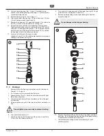
  14.  Unscrew lower housing (Fig. 13, Item 10) with adjusting 

wrench while holding the upper housing (11) securely with a 

second adjusting wrench.

  15.  Remove bearing ring (13) and O-ring (12).
  16.  Screw out outlet valve housing (14) from the piston (15) with 

3/8 inch hexagon socket head wrench.

  17.  Remove the upper seal (16), upper ball guide (17), outlet valve 

ball (18), washer (19) and outlet valve seating (20).

  18.  Clean all the parts with the corresponding cleaning agent. 

Check outlet valve housing (14), outlet valve seat (20), outlet 

valve ball (18) and upper ball guide (17) for wear and replace 

parts if necessary. If the worn outlet valve seat (20) is unused 

on one side, install it the other way around.

  19.  Carry out installation in the reverse order.
 

  Lubricate O-ring (12) with machine grease and ensure proper 

seating in the lower housing (10).

11

15

16
17
18
19

20
14
12
13

10

11.3   Packings

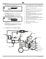
  1.  Remove inlet valve housing in accordance with the steps in 

Chapter 11.2, Page 16.

  2.  It is not necessary to remove the outlet valve.
  3.  Loosen lock nut (Fig. 14, Item 5) counterclockwise with light 

blows from a hammer.

  4.  Unscrew upper housing (6) counterclockwise from the gear 

unit housing.

  5.  Clamp upper housing (6) at the wrench surfaces vertically in a 

vice.

Attention

Do not tighten vice excessively to prevent crushing.

  6.  Screw out threaded joint (7).
  7.  Slide the piston rod (4) forward until the piston is out of the 

T-slot (2) on the slider assembly (3).  

  8.  Push piston (4) downward out of the upper housing (6). Check 

piston for wear and replace if necessary.

  9.  Remove upper packing (8) and lower packing (9) from the 

upper housing (6).

Attention

Do not damage inside of upper housing.

3

1

2
5

7

10
8

9

6

4

11

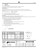
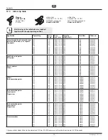
  10.  Remove the transportation devices from the upper and lower 

packings.  (The transportation device from the upper packing 

is required for installation of the piston.)

  11.  Lubricate upper packing (8) and lower packing (9) with 

machine grease.

Summary of Contents for ProSpray 3.21

Page 1: ...Edition 5 2014 0558 934G ProSpray 3 29 3 31 GB Operating manual ProSpray 3 29 3 31 Airless high pressure spraying unit Models 0558023 0558044 0558051 0558024 0558052 0558391 Original operating manual...

Page 2: ...doctor about the coating material or solvent used The operating instructions state that the following points must always be observed before starting up 1 Faulty units must not be used 2 Secure WAGNER...

Page 3: ...praying technique 12 6 Handling the high pressure hose 12 7 Interruption of work 12 8 Cleaning the unit shutting down 13 8 1 Cleaning unit from outside 13 8 2 Cleaning the high pressure filter 13 8 3...

Page 4: ...must be rated at or above the maximum operating pressure range of the sprayer This includes spray tips guns extensions and hose HAZARD High Pressure Hose The paint hose can develop leaks from wear ki...

Page 5: ...rer s instructions for safe handling of paint and solvents Clean up all material and solvent spills immediately to prevent slip hazard Wear ear protection This unit can produce noise levels above 85 d...

Page 6: ...rial by suction and conveys it to the tip Pressed through the tip at a pressure of up to a maximum of 221 bar 22 1 MPa the coating material is atomised This high pressure has the effect of micro fine...

Page 7: ...Glide EasyGlide prevents increased wear of the packings 4 Oil level gauge 5 Pail hook 6 Oil button 7 Suction tube 8 Return hose 9 Cart 10 Relief valve Lever position vertical PRIME k circulation Lever...

Page 8: ...r 3 6 Transportation Pushing or pulling the unit Pull out the handle Fig 2 Item 1 until it will come no further Insert the handle push the buttons 2 on the spars and then push in the handle 2 1 2 3 7...

Page 9: ...MPa 120 bar and 23 MPa 230 bar A solid green pressure indicator means The sprayer is at the proper pressure setting for spraying oil based and latex house paints The sprayer is operating at peak perfo...

Page 10: ...the functionality of the sprayer It is installed directly below the pressure control knob on the control panel It consists of a display and four function keys The display shows various menu screens t...

Page 11: ...will reset the Service and Run Hours displayed on the Service Screen back to 0 Security Code Screen SECURITY CODE CHANGE 2 MENU 1 The Security Code screen allows the user to set a four digit security...

Page 12: ...pair defective high pressure hoses yourself The high pressure hose is to be handled with care Avoid sharp bends and folds the smallest bending radius is about 20 cm Do not drive over the high pressure...

Page 13: ...ition PRIME k circulation 8 Pump a suitable cleaning agent in the circuit for a few minutes 9 Close the relief valve valve position SPRAY p spray 10 Pull the trigger of the spray gun 11 Pump the remai...

Page 14: ...kings sticky or worn 7 Valve balls worn 8 Valve seats worn Measures for eliminating the malfunction 1 Check voltage supply 2 Turn up pressure control knob 3 Replace 1 Set relief valve to PRIME k circu...

Page 15: ...relieve any pressure remaining in the system valve position PRIME k Additionally follow all other warnings to reduce the risk of an injection injury injury from moving parts or electric shock Always...

Page 16: ...outlet valve 1 Remove the four screws in the front cover and then remove the front cover Danger of crushing do not reach with the fingers or tool between the moving parts 2 Turn the pressure control...

Page 17: ...16 17 18 19 20 14 12 13 10 11 3 Packings 1 Remove inlet valve housing in accordance with the steps in Chapter 11 2 Page 16 2 It is not necessary to remove the outlet valve 3 Loosen lock nut Fig 14 It...

Page 18: ...21 Slide the top of the piston 4 into the T slot 2 on the slider assembly 3 22 Screw lock nut 5 at the upper housing 6 until it touches 23 Lubricate the threading of the upper housing 6 with machine g...

Page 19: ...n the relief valve handle fully counterclockwise k Circulation 2 Switch off the gasoline engine 3 Dismount the tip from the spray gun 4 Place tip in an appropriate cleaning agent until all coating mat...

Page 20: ...ed red red red red red 0553113 0553213 0553313 0553413 0553513 0553613 0553813 Fillers Rust protection paints 115 215 315 415 515 615 715 815 10 20 30 40 50 60 70 80 0 015 0 38 0 015 0 38 0 015 0 38 0...

Page 21: ...e white white white white white white white white white white white white white white white white white white white white white white white white white white white white white white white white white...

Page 22: ...interior No cleaning necessary during work stoppage or change of location because the paint in the pump cannot dry out or leak Better protection Simple assembly Suitable for the following models Diaph...

Page 23: ...060 Gessate MI Italia Tel 39 02 9592920 1 Telefax 39 02 95780187 info wagnercolora com CH Wagner International AG Industriestrasse 22 9450 Altst tten Schweiz Tel 41 71 7 57 22 11 Telefax 41 71 7 57 22...

Page 24: ...24 ProSpray 3 29 3 31 Accessories illustration ProSpray 3 29 3 31 3 1 5 7 2 4 6 8...

Page 25: ...ng high pressure hoses 1 4 x 1 4 6 0034 950 Metex Reuse Reuse for pre filtering of coating material in vessel Place suction pipe in the reuse 0034 952 Sieve package 5 pcs for paint 0034 951 Sieve pack...

Page 26: ...9 3 31 Spare parts list ProSpray 3 29 3 31 1 18 24 25 26 27 28 23 13 12 11 14 15 16 17 19 20 21 22 9 10 3 4 7 8 52 30 29 5 6 2 31 32 33 2 42 43 39 40 41 35 34 38 36 37 Main Assembly 45 46 47 50 51 44...

Page 27: ...Fluid section assembly 29 0507 783 Clip Item Part No Description 30 0507 782 Suction tube 31 0290 253 Grommit 32 0551 778 Transducer assembly 33 9805 348 Screw 4 34 0290 252 Control panel cover with l...

Page 28: ...28 ProSpray 3 29 3 31 Spare parts list ProSpray 3 29 3 31 1 2 5 6 3 4 12 13 14 15 16 17 18 7 8 9 10 19 20 21 22 11 9 10 23 24 Fluid section...

Page 29: ...07 734 Upper seal 14 0507 452 Upper ball guide 15 9841 502 Outlet valve ball 16 0507 454 Washer 17 0294 516 Outlet valve seat 18 0507 733 Outlet valve retainer 19 0507 729 Lower ball guide 20 51519 In...

Page 30: ...30 ProSpray 3 29 3 31 Spare parts list ProSpray 3 29 3 31 1 2 3 4 5 6 8 9 10 11 7 12 14 15 16 16 13 Drive Assembly...

Page 31: ...bly 5 0290 240 1st stage gear 6 0290 287 Motor assembly 7 0508 559 Screw 6 8 0558 558 Baffle assembly 9 0509 218 Screw 4 10 0558 541 Electronic control assembly PS 3 29 0558 542 Electronic control ass...

Page 32: ...esh standard 0508 451 Filter 30 mesh 0508 452 Filter 100 mesh 4 0508 603 Bearing ring 5 0508 749 Bearing spring 6 0551 951 O ring 7 0507 739 Pipe plug Item Part No Description 8 0290 264 Housing 9 050...

Page 33: ...ay 3 29 1 2 3 4 5 Suction system for low boy cart Spare parts list Item Part No Description 1 0507 964 Return hose 2 0507 965 Siphon tube 3 5006 536 Inlet screen 4 0507 783 Clamp 5 0507 967 Siphon tub...

Page 34: ...805 352 Screw 2 3 0290 257 Bushing 4 0290 235 Cart weldment 5 9894 275 Spring 6 0290 294 Bushing 7 0290 244 Carriage assembly 8 0509 386 Washer 4 9 0295 608 Screw 4 10 0279 481 Screw Item Part No Desc...

Page 35: ...Description 1 0290 290 Cart 2 0508 381 Drip cup 3 0290 291 Wheel 4 0294 534 Wheel spacer 5 9890 104 Axle cap 6 9805 230 Drip cup screw 7 0509 386 Washer 8 0295 608 Screw 9 9885 571 Plug 10 0294 635 P...

Page 36: ...product has to be sent without charge or presented together with the original purchase document that includes details of the purchase date and the name of the product In order to claim for an extensi...

Reviews: