background image

4 Commissioning [specialist] 


2015/03 

EN-XXX_CIRCOtransfer-30E-50E_TI-MA-BA-150401-3PAW0501 - 99609x7WAG0x-mub-en - V06 

15 

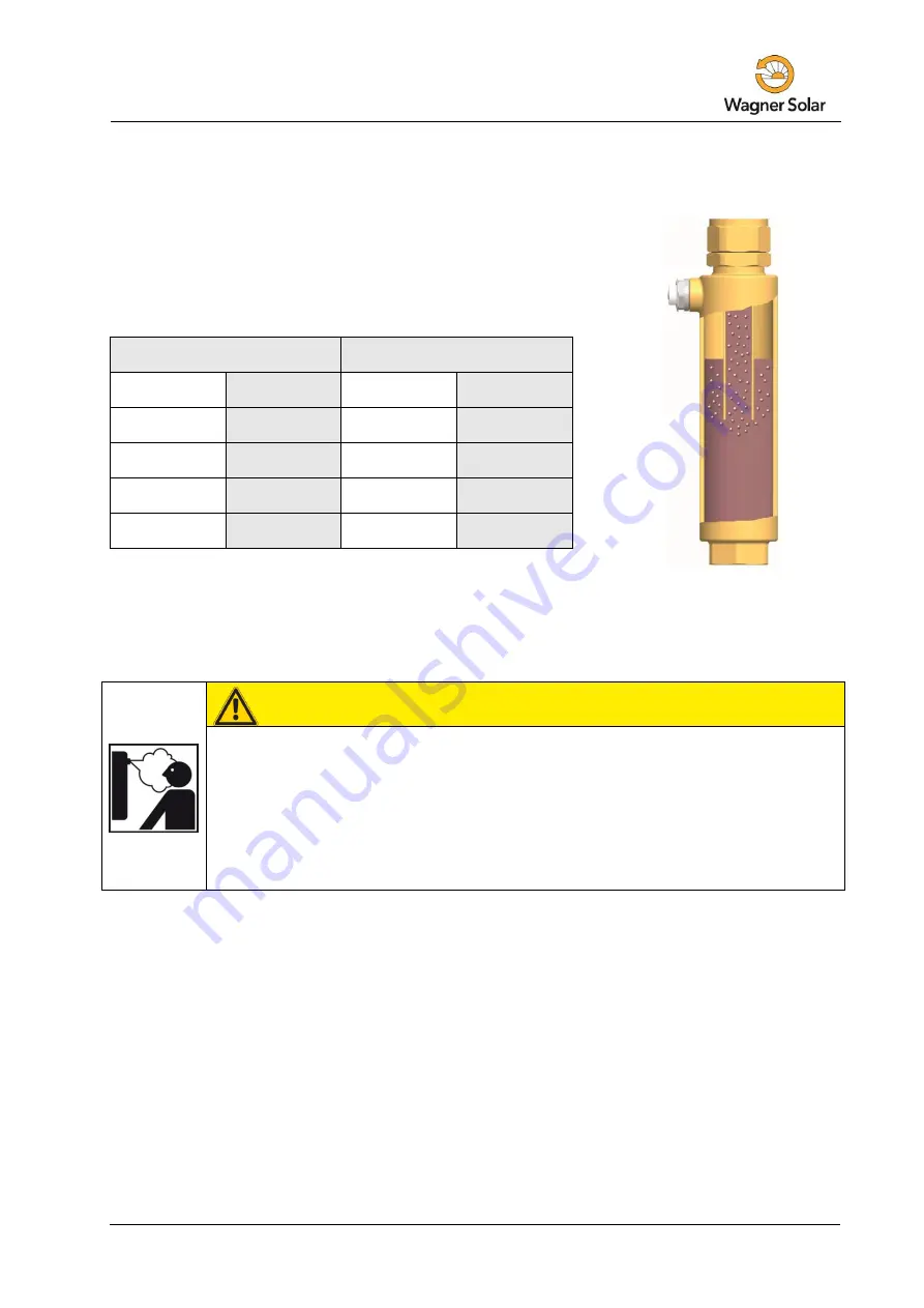
Airstop 

The Airstop (air-scoop with plug for manual venting) serves to 
bleed the solar installation. To ensure perfect deaeration of the 
solar circuit, the flow velocity must be at least 0.3 m/s in the  
flow line. 


Pipe diameter [mm] 

Flow rate at 0.3 m/s 

∅ outside 

∅ inside 

l/h 

l/min 

15 

13 

~ 143


~ 2.4 

18 

16 

~ 217 

~ 3.6 

22 

20 

~ 339 

~ 5.7 

28 

25 

~ 530 

~ 8.8 

The air separated from the solar fluid is collected in the upper part of the Airstop and can be 
released at the vent plug [j]. 


WARNING 

Danger of scalding due to vapour escape! 

The escaping fluid can have a temperature of more than 100 °C and cause 
scalding. 


Carefully open the vent plug and close it again, as soon as medium 
escapes. 


Venting the solar installation after commissioning 

At the beginning, vent the solar installation daily and then weekly or monthly, 
depending on the vented air quantity. Thus, an optimum operation of the solar 
installation is ensured. Check the system pressure after venting and increase it to  
the specified operating pressure, if necessary. 


Summary of Contents for 150 202 20

Page 1: ...CIRCOtransfer 30E 50E_TI MA BA 150401 3PAW0501 99609x7WAG0x mub en V06 1 Installation and Operation Instructions Transfer stations CIRCOtransfer 30 E CIRCOtransfer 50 E Hydraulics CIRCOtransfer 30 E CIRCOtransfer 50 E ...

Page 2: ...XX_CIRCOtransfer 30E 50E_TI MA BA 150401 3PAW0501 Item no 99609x7WAG0x mub en Version V06 Issued 2015 03 Translation of the original instructions We reserve the right to make technical changes without notice Printed in Germany Copyright by Wagner Solar GmbH Wagner Solar GmbH Industriestraße 10 D 35091 Cölbe Germany ...

Page 3: ... circuit 14 4 4 Maintenance specialist 19 4 5 Draining the solar installation 20 4 6 Deinstallation 20 5 Spare parts specialist 21 5 1 Spare parts primary circuit CIRCOtransfer 30 E 15020220 21 5 2 Spare parts secondary circuit CIRCOtransfer 30 E 15020220 22 5 3 Spare parts primary circuit CIRCOtransfer 50 E 15020221 23 5 4 Spare parts secondary circuit CIRCOtransfer 50 E 15020221 24 6 Technical d...

Page 4: ...nction installation commissioning and operation of the transfer stations CIRCOtransfer 30 E and CIRCOtransfer 50 E The chapters called specialist are intended for specialists only For other components of the installation such as pumps controllers or the distribution manifold see the manufacturers instructions CIRCOtransfer 30 E item number 150 202 20 Power kW Collector surface m Low flow 17 l m h ...

Page 5: ...y circuit Pressure relief valves to prevent inadmissible overpressures Pressure gauge to display the system pressure in the solar circuit Vent valves to easily vent the solar circuit Fill and drain valves to flush fill and drain the solar circuit Two flow meters and electronic temperature sensors for heat quantity balancing secondary and speed control of the pumps depending on the performance The ...

Page 6: ...alues indicated in these instructions Due to its design the station must be mounted and operated as described in these instructions Only use original accessories with the transfer station Improper usage excludes any liability claims When the sun shines the collectors can become very hot The solar fluid in the circuit can heat up to more than 100 C Only flush and fill the solar circuit when the col...

Page 7: ... national regulations accident prevention regulations of the professional association instructions and safety instructions mentioned in this manual WARNING Danger of scalding due to vapour escape With pressure relief valves there is risk of scalding due to vapour escape During installation check the local conditions and if a discharge line must be connected to the safety group Observe the instruct...

Page 8: ...ry or damage to property Only close the ball valves for service and maintenance NOTICE Material damage due to mineral oils Mineral oil products cause lasting damage to seals made of EPDM whereby the sealant properties get lost We do not assume liability nor provide warranty for damage to property resulting from sealants damaged in this way It is imperative to avoid that EPDM gets in contact with s...

Page 9: ...o the environment and to easily refill the circuits NOTICE Material damage due to high temperatures Install the fitting group at a sufficient distance from the collector field since the solar fluid may be very hot near the collector It may be necessary to install an intermediate tank in order to protect the expansion tank 1 You can use a drilling template in order to facilitate the installation wh...

Page 10: ...g of the pressure relief valve c the fill valve d and the pressure gauge e to the connection of the return ball valve b 9 Connect the expansion tank below the pressure gauge e During servicing at the expansion tank we recommend the installation of a cap valve on the expansion tank NOTICE Note regarding the expansion tank The expansion tank must not be connected while flushing and filling in order ...

Page 11: ...You can find a detailed description for the operation of the controller in the separate controller manual WARNING Risk to life and limb due to electric shock Prior to commencing electrical work on the controller pull the mains plug Only after completing all installation work flushing and filling plug the mains plug of the controller into a socket Thus an unintentional start of the motors is avoide...

Page 12: ...70 C CAUTION Risk of frost It often happens that the solar thermal system cannot be completely drained after flushing Thus there is risk of frost damage when flushing with water Therefore do only use the solar fluid used later to flush and fill the solar installation Use a water and propylene glycol mixture with max 50 of propylene glycol as solar fluid CAUTION Note regarding the commissioning seq...

Page 13: ... system To avoid that dirt particles are washed into the heat exchanger close the ball valves of the station and wash out the present dirt particles and scale residues before commissioning the tank Make sure to only use purified heating water according to VDI 2035 Ö Norm H 5195 1 1 Open the ball valves D E and put the check valves out of operation 45 see next page 2 Vent the storage tank circuit b...

Page 14: ...exchanger and the expansion tank Disconnect the expansion tank from the solar circuit during flushing and filling if necessary and only use flush and fill stations with fine filters The solar circuit is flushed in the direction of flow Make sure that the pump in the solar circuit cannot be switched on Ball valve with integrated flow check valve normal flow direction in the figure below downwards 0...

Page 15: ...separated from the solar fluid is collected in the upper part of the Airstop and can be released at the vent plug j WARNING Danger of scalding due to vapour escape The escaping fluid can have a temperature of more than 100 C and cause scalding Carefully open the vent plug and close it again as soon as medium escapes Venting the solar installation after commissioning At the beginning vent the solar...

Page 16: ...lve h 4 Open the fill and drain valves d h and put the flush and fill station into operation 5 Slowly open and close the return ball valve b and the drain valve k during flushing in order to vent the pump section 6 Flush the solar circuit until the solar fluid exits without bubbles see page 15 7 Close the drain valve h with the filling pump running and increase the system pressure to about 5 bars ...

Page 17: ... position see page 14 WARNING Risk to life and limb due to electric shock Check if the sensors and the pumps are properly connected to the controller and if the controller housing is closed Only then should the mains plug of the controller be plugged into a socket 14 Connect the optional controller to the mains and set the solar circuit pump to ON in the manual mode according to the controller ins...

Page 18: ...e fill and drain valves The sealing caps only serve to protect the valves against dirt They are not designed to take up high system pressures The ball valves must be closed 18 Mount the insulating front shell 19 Set to automatic mode on the controller see controller instructions The commissioning of the solar installation is now completed Please fill in completely the commissioning report on page ...

Page 19: ...ratures of more than 100 C The solar fluid can escape as vapor and cause scalding Only carry out maintenance work when the collector temperatures are below 50 C Wait until the solar fluid has cooled down to max 50 C Example CIRCOtransfer 30 E 1 Close the ball valves a b and drain the solar fluid at the drain valve h Make sure that the solar fluid is collected in a heat resistant container 2 Change...

Page 20: ...he escaping fluid may be very hot Place and fix the heat resistant collecting container so that people standing nearby are not endangered when the solar installation is being emptied 4 Open the drain valve h of the transfer station 5 To accelerate draining of the solar circuit you can open the bleeding device if present at the highest point of the solar thermal system 6 Dispose of the solar fluid ...

Page 21: ...Complaints and requests orders of spare parts will only be processed with information on the serial number The serial number is placed in the lower right corner of the support sheet of the station In case of a complaint please send us the completely filled commissioning report on page 31 5 1 Spare parts primary circuit CIRCOtransfer 30 E 15020220 ...

Page 22: ...5 Spare parts specialist 22 EN XXX_CIRCOtransfer 30E 50E_TI MA BA 150401 3PAW0501 99609x7WAG0x mub en V06 2015 03 5 2 Spare parts secondary circuit CIRCOtransfer 30 E 15020220 ...

Page 23: ...5 Spare parts specialist 2015 03 EN XXX_CIRCOtransfer 30E 50E_TI MA BA 150401 3PAW0501 99609x7WAG0x mub en V06 23 5 3 Spare parts primary circuit CIRCOtransfer 50 E 15020221 ...

Page 24: ...5 Spare parts specialist 24 EN XXX_CIRCOtransfer 30E 50E_TI MA BA 150401 3PAW0501 99609x7WAG0x mub en V06 2015 03 5 4 Spare parts secondary circuit CIRCOtransfer 50 E 15020221 ...

Page 25: ...t pressure relief valve internal thread Operating data Max admissible pressure 6 bars Max operating temperature 120 C Max stagnation temperature 140 C Max propylene glycol content 50 Operating temperature sensors 25 C to 120 C Equipment Pressure relief valve prim 6 bars sec 6 bars Pressure gauge 0 6 bars Flowmeter 2 x Flowmeter 3 22 l min 2 x Flowmeter 5 40 l min Sensors 3 PT1000 mounted 3 PT1000 ...

Page 26: ...6 Technical data 26 EN XXX_CIRCOtransfer 30E 50E_TI MA BA 150401 3PAW0501 99609x7WAG0x mub en V06 2015 03 6 1 Dimensional drawing CIRCOtransfer 30 E ...

Page 27: ...6 Technical data 2015 03 EN XXX_CIRCOtransfer 30E 50E_TI MA BA 150401 3PAW0501 99609x7WAG0x mub en V06 27 6 2 Dimensional drawing CIRCOtransfer 50 E ...

Page 28: ...0E_TI MA BA 150401 3PAW0501 99609x7WAG0x mub en V06 2015 03 6 3 Pressure drop characteristics CIRCOtransfer 30 E Pressure m wc Pressure kPa Flow rate m h 6 4 Pressure drop characteristics CIRCOtransfer 50 E Pressure m wc Pressure kPa Flow rate m h ...

Page 29: ...sufficient you need to install additional components to prevent gravity circulation You can mount components such as syphons heat traps 2 way valves zone valves or additional check valves Example The station comprises two check valves 2 x 200 mm wc 400 mm wc You use a mixture of water and 40 of propylene glycol as a solar fluid The installation height between the collector and the storage tank is ...

Page 30: ...fferences the difference in density will cause gravity circulation Calculation example Δp Δρ g h Collector temperature 5 C Density solar fluid ρ1 1042 kg m Storage tank temperature 67 C Density solar fluid ρ2 1002 5 kg m Δρ ρ1 ρ2 39 5 kg m g 9 81 m s Installation height h 10 m Δp 3875 Pa 395 mm wc The two check valves in the station 2 x 200 mm wc are sufficient for an installation height of 10 m a...

Page 31: ...ght between station and collector field Pipes mm l m Venting collector field Not existent Vented Manual vent valve Automatic deaerator Airstop station Vented Solar fluid type glycol Antifreeze tested up to C Serial numbers Flow rate l m Station Pump type Flow rate sensor System pressure mbars Temperature sensor Expansion tank type Initial pressure mbars Controller Pressure relief valve Checked Che...

Page 32: ...XXX_CIRCOtransfer 30E 50E_TI MA BA 150401 3PAW0501 99609x7WAG0x mub en V06 2015 03 Wagner Solar GmbH Industriestraße 10 D 35091 Cölbe Germany www wagner solar com Tel 49 0 6421 8007 0 Fax 49 0 6421 8007 22 ...

Reviews: