background image

EN

G

LIS

H

9

User’s Manual—Read before using this equipment

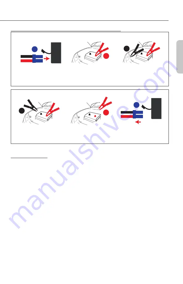
Brief Recap of Sequences for Connection and Disconnection

2

3

1

ORDER OF CONNECTION

2. Connect positive (red)

clamp to positive battery

terminal.

1. Connect cables to iOnBoost.

3. Connect negative (black)

clamp to solid metal ground

on engine or frame, away

from battery).

1

2

3

ORDER OF DISCONNECTION

2.

Disconnect positive

(red) clamp from positive 

battery terminal.

1.

Disconnect negative

(black) clamp

from frame.

3.

Disconnect cables from

iOnBoost.

READ THE REMAINDER OF THE INSTRUCTIONS BEFORE USING THE IONBOOST!

Jumpstart Procedure

1. Turn off the vehicle ignition and all accessories (radios, lights, air conditioners), and disconnect

electronic devices.

2. Set the emergency brake and put vehicles with automatic transmission in park position.
3. Determine the polarity of the vehicle’s battery terminals. The positive (POS, P, +) battery

terminal usually is red and larger in diameter than the negative (NEG, N, −) terminal. If you

are unsure, first refer to the vehicle owner’s manual. Make sure the negative battery terminal is

also connected to the vehicle frame.

4. If engine was recently cranked, use a non conductive material (cardboard or a folded

newspaper) to wave away (dispel) explosive gases. Do this for a few minutes before any

vehicle connections.

5. Insert the blue plug of the jumper cables into the iOnBoost’s jumper terminal. When fully

inserted, the red and green lights on the cable safety block should both flash continuously.

Never allow clamps (positive & negative terminals) to touch together or contact the same

piece of metal to prevent short-circuits and arcing�

6. Securely connect the positive (+) red clamp to the positive (POS, P, +) terminal of the vehicle

battery or the remote positive (+) terminal if equipped.

7. Securely connect the negative (−) black clamp to a non-moving, metal part of the engine or

frame as far away from the vehicle battery as possible.

Summary of Contents for iOnBoost V8

Page 1: ...Item No 7502 User s Manual We are constantly improving our products so specifications are subject to change without notice BC LITHIUM JUMP STARTER POWER BANK...

Page 2: ...t Information 4 General Warnings 4 Features 4 Specifications 5 Care Maintenance 5 Charging the iOnBoost 7 Jumpstarter 8 Troubleshooting 10 DC Power Port 10 Using the USB Socket 11 LED Flashlight 11 Pr...

Page 3: ...er and safe operation of any accessory outlet do not place anything in it except the plug of the accessory to be used Use only the charging adapters and jumpstarting clamps provided in this package Un...

Page 4: ...Battery capacity watt hours 47 4 Wh Peak amps 500 A Cranking amps 300 A Jumper cables 10 AWG 8 inch DC Accessory Outlet 12V 16V 19V USB power port 5V 2 1 A Flashlight LED with 3 lighting modes Operati...

Page 5: ...rt 4 Battery status indicator 5 Multifunction MODE button 6 USB power port 7 Charging Jack 8 Master power switch 9 Jumper terminal 10 Cable safety block 11 Battery connection warning lights 12 Carryin...

Page 6: ...lights illuminate solid 4 When charging is complete unplug the AC charging adapter from the wall socket first then from the charging jack on the unit 5 The battery status can be checked by tapping on...

Page 7: ...he frame Make sure the jumpstarter clamps get connected to correct polarity red to positive battery terminal black to vehicle frame for negative ground systems when jumpstarting Use safety glasses to...

Page 8: ...s The positive POS P battery terminal usually is red and larger in diameter than the negative NEG N terminal If you are unsure first refer to the vehicle owner s manual Make sure the negative battery...

Page 9: ...each other 13 Disconnect the jumper cable assembly from the unit 14 When convenient using either AC or DC charging adapter completely charge the iOnBoost battery 15 Store the unit and charge adapters...

Page 10: ...THE USB SOCKET If the charge in the iOnBoost is low the USB port will shut off to prevent damage to the iOnBoost Recharge the iOnBoost as soon as convenient 1 Connect the USB device to the iOnBoost w...

Page 11: ...xpressed or implied and no representative or person is authorized to assume any other liability in connection with the sale of our products There shall be no claims for defects or failure of performan...

Reviews: