background image

5

Quick Start

Unpacking and Placement

Unpack each of the cartons. Check each component for shipping damage and verify that the operating voltage
matches your local AC voltage. The Wadia 931 Digital Controller should be positioned near the source components,
the Wadia 921 Mono Decoding Computers should be placed near the amplifier or amplifiers.

Connections

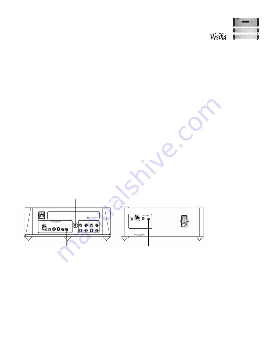
Use the illustrations below and on the following page to connect the Wadia series 9 Decoding Computer
System. All rear-panel connectors are labeled. Input 1 on the 931 Digital Controller is configured for ClockLink.
If you are using a source component equipped with ClockLink, such as the Wadia 270 CD transport, connect it
to Input 1. Non-ClockLink sources should not be connected to ClockLink inputs. For instructions to configure
any input to turn ClockLink on or off, see

Configurations

on page 22.

Level Setting

The Maximum Output Level can be set to match the sensitivity of your loudspeaker, room size, and listening
preference. The Wadia 921 Mono Decoding Computers come shipped from the factory with the output level set
at 2 volts RMS. For instruction on how to configure the output voltage see

Output Level Settings

on page 13.

Operation

The Wadia 931 Digital Controller acts as the user-interface for the entire Wadia series 9 Decoding Computer
System and uses remote commands and operations that are similar to other Wadia products. For a full list of
instructions, refer to

Operations

on page 16.

ClockLink Cable

Data Cable

Wadia 931 Digital Controller

ClockLink-Equiped Digital Source

Summary of Contents for 931

Page 1: ...931 921 Decoding Computer System Information Operation Manual...

Page 2: ...931 921 Decoding Computer System...

Page 3: ...ated Status Indicator 13 Maximum Output Level Setting 13 Choosing a Digital Cable 14 Frequently Asked Questions 15 Operation and Configuration Front Panel Controls 16 Remote Control Commands 17 Operat...

Page 4: ...abbreviated list of the technological innovations Wadia engineers have pioneered First company to introduce an outboard Digital to Analog converter First company to develop an audio optimized upsampli...

Page 5: ...erience installing configuring and operating Wadia components you can use the Quick Start section and refer to the complete instructions where needed Inventory Before proceeding please check to make s...

Page 6: ...t it to Input 1 Non ClockLink sources should not be connected to ClockLink inputs For instructions to configure any input to turn ClockLink on or off see Configurations on page 22 Level Setting The Ma...

Page 7: ...kLink output 2 from the Wadia 931 Digital Controller to the ClockLink input of the left channel Wadia 921 Mono Decoding Computer Step 3 Connect data output 3 from the Wadia 931 Digital Controller to t...

Page 8: ...ng it nearby these units Wadia 921 Mono Decoding Computers The Wadia 921 Mono Decoding Computers should be placed as near to the amplifier or amplifiers as possible This will allow you to use shorter...

Page 9: ...a 270 CD Transport Using a non ClockLink source connected to a ClockLink input degrades the sonic performance To change the configuration of any input see Configuring Inputs on page 26 Any digital sou...

Page 10: ...ock and is further enhanced by a superior power supply The Wadia 931 Digital Controller has a ClockLink output for source components such as a Wadia 270 CD Transport To link the Wadia 270 CD transport...

Page 11: ...1 Digital Controller to be used in a variety of system configurations To change the configuration of the outputs see Configurations on page 24 Wadia 931 Digital Controller digital outputs Wadia 921 De...

Page 12: ...3 from the Wadia 931 Digital Controller to the data input of the right channel Wadia 921 Mono Decoding Computer Step 4 Connect ClockLink output 4 from the Wadia 931 Digital Controller to the ClockLin...

Page 13: ...e that your power amplifier is turned off then connect your analog interconnects from the Wadia 921 Mono Decoding Computers balanced or unbalanced analog outputs to the amplifier s inputs Connecting t...

Page 14: ...ge above 70 The Maximum Output Level is adjusted by means of a set of switches located on the back panel of the Wadia 931 Decoding Computer with 4 4 Volts RMS being the loudest setting If more than on...

Page 15: ...cal cable The quality of any of these transmission methods depends on the quality of the cable and the sophistication of the transmitter and receiver For example a high quality coaxial cable can outpe...

Page 16: ...921 Mono Decoding Computer output stage is capable of driving both types of outputs simultaneously Why should I bypass the Preamplifier A preamplifier is unnecessary when using your Wadia series 9 Dec...

Page 17: ...five buttons on the front panel of the Wadia 931 Digital Controller During configuration mode these buttons change functions see Configuration UP Down These buttons perform the same function as the vo...

Page 18: ...een normal and inverted phase Display On Off Changes between Display on and off Modes In display off mode the display is off but turns on for 5 seconds whenever any key is pressed In display on mode t...

Page 19: ...on Mode screen by pressing enter either on the front panel or the remote control After 10 seconds of no user activity the display will revert to the main screen W a d i a 9 3 1 D i g i t a l C o n t r...

Page 20: ...play looks like this The balance control setting does not affect the volume control setting or the volume value displayed Pressing either balance key on the remote causes the display to jump to the ba...

Page 21: ...olume is set to zero by sending a stream of zero data to the output or by interrupting the output When entering or leaving mute mode the volume ramps up or down such that it takes roughly 2 seconds to...

Page 22: ...he new sample rate for approximately 2 seconds Emphasis Detect Discs recorded with digital emphasis are automatically detected and this is displayed by switching to the Status Screen for approximately...

Page 23: ...figuration mode the front panel controls change function The left right up and down keys are used to position the cursor enter is used to make your selection and move to the next screen Menu Screen Ma...

Page 24: ...23 Configuration Menu Screen Map...

Page 25: ...the next screen Wadia 931 Digital Controller Inputs Input 1 GFO Input 2 GFO Input 3 BNC Input 4 BNC Input 5 Toslink Input 6 XLR AES Configuring Input ClockLink On or Off If you are using a source equ...

Page 26: ...ess the enter key to move to the next screen Configuring Outputs You can configure the Wadia 931 Digital Controller outputs to be either ClockLink Output If you are connecting this output to a ClockLi...

Page 27: ...ut 2 and press the enter key Choose the desired setting for this output As shown below output 2 is configured to be a right channel mono output Wadia 931 Digital Controller Outputs Output 1 Left Chann...

Page 28: ...r will revert to the last saved settings If none have ever been saved it will revert to the factory default settings Once you have saved new configuration settings they will remain in effect until new...

Page 29: ...is copyrighted and patented It is the property of Wadia Digital Title to Licensed Software is not transferred to the customer The customer is granted a nonexclusive license to use the Licensed Softwa...

Page 30: ...ber Clock or Data Analog Outputs 921 One pair of Balanced XLR One pair of Unbalanced RCA Both can be used simultaneously Output Type Class A Zero Global Feedback Circuit Bipolar Output Device Volume C...

Page 31: ...rity of your home s electrical system contact a licensed electrician for assistance 4 AC extension cords are not recommended for use with this product If an extension cord must be used be sure it is a...

Page 32: ...ges from Wadia 5 Wadia shall not under any circumstances be liable for any incidental or consequential damages arising from the loss of property or other damage or losses due to the failure of a Wadia...

Page 33: ...w w w w a d i a c o m...

Page 34: ......

Reviews: