


Schematics
E 1100
148
wc_tx001908gb.fm
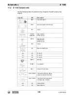
11.2
E 1100 Components
Use the following table of symbols for the schematics found throughout this
chapter.
Symbol
Ref
Description
CB1
Circuit breaker 1
GFCI
Ground Fault Circuit Interrupt
FU1
Fuse 1
HOSE
REWIND
Hose rewind
Off/On switch
MTR
Rewind motor
Pump motor
Burner motor
FU2
Fuse 2
n/a
Rewind transformer
n/a
n/a
To line 14
n/a
n/a
To line 16
n/a
n/a
To line 24
RECT1
Rectifier
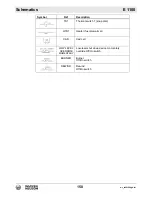
FTSW1
Foot switch 1
SOL1
Solenoid 1 (oil valve)
LOW LEVEL
Low-level shut-down device
power connection terminals
LOW LEVEL
Low-level shut down device
normally open contacts
n/a
n/a
Pumps Motor
n/a
n/a
Rewind Motor
Summary of Contents for E1100
Page 19: ...E 1100 Safety Information wc_si000628gb fm 19 Notes...
Page 20: ...Labels E 1100 20 wc_si000629gb fm 2 Labels 2 1 Label Locations wc_gr009588...
Page 105: ...ghi_tx001153gb fm 105 E 1100 Maintenance...
Page 122: ...Technical Data E 1100 122 wc_td000476gb fm 10 5 Dimensions cm in wc_gr008706...
Page 133: ...wc_tx001673gb fm 133 Fuji Temperature Controller...
Page 134: ...wc_tx001673gb fm 134 Fuji Temperature Controller...
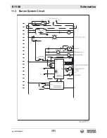
Page 151: ...E 1100 Schematics wc_tx001908gb fm 151 11 3 Burner System Circuit...
Page 152: ...Schematics E 1100 152 wc_tx001908gb fm 11 4 Circulation System Circuit ghi_gr005662...
Page 153: ...E 1100 Schematics wc_tx001908gb fm 153 11 5 Rewind System Circuit...
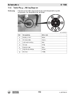
Page 158: ...Schematics E 1100 158 wc_tx001908gb fm 11 10 Genset DC Wiring Diagram...
Page 160: ......
Page 161: ......