


3-4
OM 25-3503 us – Edition 4.1 * * 2503_3503b320.fm
Operation
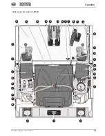
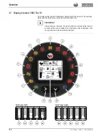
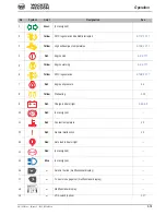
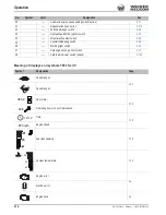
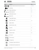
3.1 Cabin overview
Pos.
Description
For more information see page
1
Control lever (left)
..............................................................................................................................................................3-72
2
Control lever (right)
............................................................................................................................................................3-77
3
Control lever base (left)
4
Control lever base (right)
5
Armrest (left)
6
Armrest on the right (not shown)
7
Lever (horizontal seat adjustment)
.......................................................................................................................................3-4
8
Air vents
...............................................................................................................................................................................3-4
9
Radio (option)
10
Operator seat (backrest adjustment)
...................................................................................................................................3-4
11
Seat belt (lock)
.....................................................................................................................................................................3-4
12
Cup holder
13
Document storage (underneath the seat console)
14
Switch panel (right)
..............................................................................................................................................................3-4
15
Switch panel (left)
1
...............................................................................................................................................................3-4
1.
Cabin top view up to serial no. AG02452: automatic engine speed setting (from serial no. AG00580) or hydraulic quickhitch (from serial no. AG02027)
16
Throttle
...............................................................................................................................................................................3-11
17
Stabilizer-blade lever
...........................................................................................................................................................3-4
18
Auxiliary hydraulics pedal
....................................................................................................................................................3-4
19
Preheating start switch
.......................................................................................................................................................3-11
20
12 V power outlet
2
2.
Power outlet for cabin version/12 V connection for canopy version: from 1st quarter of 2015 / WNxxxxxxxxxxxxxxxxx (2503); WNxxxxxxxxxxxxxxxxx (3503)
21
Display element
...................................................................................................................................................................3-7
22
Accelerator pedal (left)
.........................................................................................................................................................3-4
23
Accelerator pedal (right)
.......................................................................................................................................................3-4
24
Drive lever (left)
....................................................................................................................................................................3-4
25
Drive lever (right)
.................................................................................................................................................................3-4
26
Immobilizer status indicator (option)
..................................................................................................................................3-23
27
Immobilizer emitter/receiver unit
........................................................................................................................................3-23
28
Changeover valve for SAE/ISO controls (option, underneath the base plate)
...................................................................3-77
29
Weight adjustment for seat
................................................................................................................................................
3-51
30
Proportional controls indicator (option)
..............................................................................................................................
3-80
31
Lever for engine and valve cover
.......................................................................................................................................
3-58
32
Hydraulic quickhitch pedal (option)
...................................................................................................................................
3-92
33
VDS button (upper carriage tilting – option 3503)
3
............................................................................................................3-87
3.
VDS operation with console switch from serial no. AG02695
Summary of Contents for 2503
Page 12: ...I 10 OM 25 3503 us Edition 4 1 Ba2503_3503us4_0SIX fm Index...
Page 40: ...1 28 OM 25 3503 us Edition 4 1 2503_3503b110 fm Introduction...
Page 182: ...4 8 OM 25 3503 us Edition 4 1 2503_3503b410 fm Malfunctions...
Page 230: ...5 48 OM 25 3503 us Edition 4 1 2503_3503b550 fm Wartung...
Page 250: ...6 20 OM 25 3503 us Edition 4 1 2503_3503b610 fm Technical datac 2503 3503 long short stick...
Page 252: ...6 22 OM 25 3503 us Edition 4 1 2503_3503b610 fm Technical datac...