POW-R-DRIVE II
16
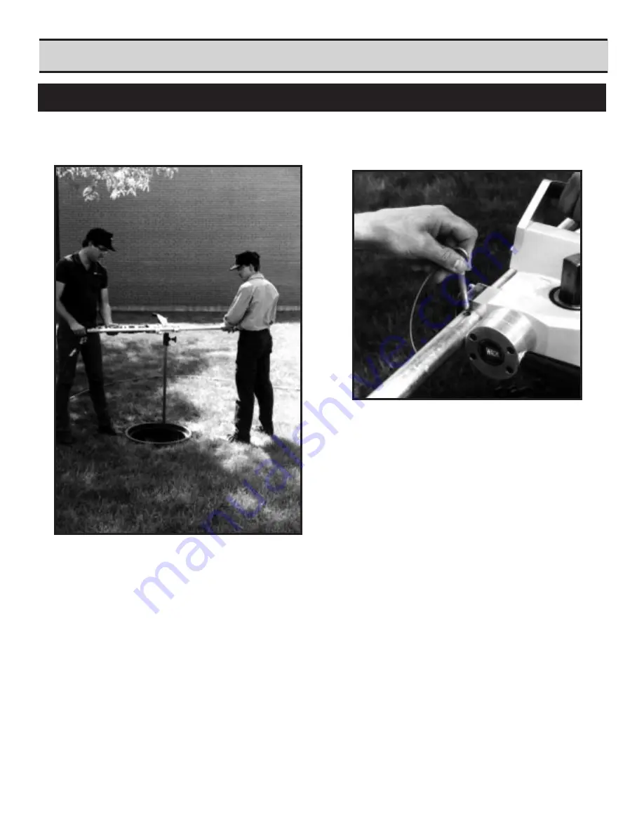
TWO OPERATOR OPERATION:
1. An extension handle is provided with each
Pow-R-Drive II. It is designed to be inserted
into the end of the handle assembly near the
powerhead (see Figure 5). A convenient
quick release pin attached to the extension
handle is inserted through the handle and
extension to secure them.
SECTION IV
SET-UP AND OPERATION
An extension handle should be used when the
torque required to turn a valve is more than one
operator can control easily.
The second operator should stand on the op-
posite side of the Pow-R-Drive II as the primary
operator. (see photograph)
The torque should be pulling the machine handle
away from both the secondary and primary
operator.
2. When the extension handle is inserted, the
machine can be used as a manual "T" wrench
if desired.
.
FIGURE 5
Summary of Contents for POW-R-DRIVE II
Page 2: ......
Page 7: ...POW R DRIVE II 7 Set Up Operating Procedures Section IV ...
Page 17: ...POW R DRIVE II 17 SECTION V MISCELLANEOUS CHARTS AND GRAPHS ...
Page 20: ......
Page 21: ...POW R DRIVE II 21 SECTION VI MAINTENANCE ...
Page 23: ...POW R DRIVE II 23 SECTION VII PARTS LISTS EXPLODED VIEW DRAWINGS ...
Page 25: ...25 ...
Page 27: ...27 ...
Page 29: ...11 080 00 181 061 041 ...
Page 31: ...31 081 ...
Page 33: ...33 081 ...
Page 35: ...35 ...
Page 37: ...37 ...
Page 38: ...POW R DRIVE II Electrical Schematics Eibenstock Milwaukee Electric RevolutionCounter Wire 38 ...
Page 39: ...39 ...
Page 40: ...POW R DRIVE II 40 SECTION VIII VALVE EXCERCISING LOG ...


