background image

34
www.nieaf-smitt.com

Safety instructions

This meter has been designed for safe use, but must be operated with  

caution. The rules listed below must be carefully followed for safe operation.

NEVER apply voltage or current to the meter that exceeds the specified 

maximum.

• 

Use extreme caution when working with high voltages. 

• 

Do 

not measure

 voltage if the voltage on the ‘COM’ input jack exceeds 

1000 V above earth ground 

• 

Never connect the meter leads across a voltage source while the func-

tion switch is in the current, resistance, or diode mode. Doing so can 

damage the meter.


Function

Maximum input

VDC or VAC

1000 VDC/DC RMS

mA AC/DC

800 mA 1000 V fast acting fuse

AAC/DC

10 A 1000 V fast acting fuse (20 A for 30 
seconds max. every 15 minutes)

Frequency, resistance, capacitance, duty 
cycle, diode test, continuity

1000 VDC/AC RMS

Temperature

1000 VDC/AC RMS


To reduce the risk of fire or electric shock do not expose this  


product to rain or moisture

Summary of Contents for 626005055

Page 1: ...Nieaf Smitt is a brand name of Wabtec NETHERLANDS NI 74 True RMS multimeter Handleiding Manual ...

Page 2: ...lic in any form or manner either electronically mechanically by photocopying recording or in any manner without prior written consent from Wabtec Netherlands B V This also applies to accompanying drawings and diagrams Due to a policy of continuous development Wabtec Netherlands B V reserves the right to alter the equipment specification and description outlined in this document without prior notic...

Page 3: ... 14 4 5 Weerstand meting 15 4 6 Continuity check 16 4 7 Diode test 17 4 8 Temperatuur meting 18 4 9 Capaciteit meting 19 4 9 Frequentie duty cycle meting 20 5 Functies 5 1 Auto handmatig bereik 20 5 2 MAX MIN 21 5 3 Relatieve mode 21 5 4 Backlight 22 5 5 Hold 22 5 6 Auto power off 22 5 7 Lege batterij 22 6 Onderhoud 6 1 Batterij vervangen 23 6 2 Zekering vervangen 24 7 Specificaties 26 ...

Page 4: ...en kunnen leiden Symbolen op de multimeter Dit symbool naast een ander symbool ingang of regelorgaan geeft dat de gebruiker de handleiding moet raadplegen om persoonlijk letsel of schade aan de meter te vermijden Het WAARSCHUWING symbool wijst op een mogelijk gevaarlijke situatie Indien de instructies niet worden gevolgd kan dit leiden tot ernstig of dodelijk letsel Het CAUTION symbool geeft een p...

Page 5: ... een meting Verricht nooit een spanningsmeting met een meetsnoer aange sloten op de A invoer Controleer de werking van de multimeter door het meten van een bekende spanning Laat bij twijfel de multimeter nakijken Pas nooit hogere spanning toe tussen de aansluitbussen of tussen een aansluitbus en aarde zoals aangegeven op de multimeter Verricht geen stroommeting in een circuit met een spanning die ...

Page 6: ...et een hoge spanning voor dat men weerstand continuïteit doorgang diodes of capaciteiten in dit circuit gaat meten Gebruik de multimeter niet in de buurt van explosieve gassen of dampen Reduceer het gevaar op elektrische schokken of brand door de multimeter niet bloot te stellen aan regen of vochtigheid Specifieke voorzorgsmaatregelen Deze meter is ontworpen voor veilig gebruik maar moet zorgvuldi...

Page 7: ...PANNINGSCATEGORIE I is apparatuur voor aansluiting op een circuit welke maatregelen worden getroffen om de transient overspan ningen te beperken tot een veilig laag niveau Overspanning categorie II Apparatuur van OVERSPANNINGSCATEGORIE II is energie verbruikende appa ratuur welke geleverd wordt door de vaste installatie Voorbeelden omvatten huishouden kantoor en laboratorium apparaten Overspanning...

Page 8: ...eerstand Duty cycle Temperatuur Kenmerken True RMS Stroommeting tot 20 A AC DC Capaciteit Doorgangs diodetest IP 67 waterdicht Min max hold Automatische uitschakeling Verlicht display Schermresolutie 6 000d Overspanningscategorie CAT III 1000 V CAT IV 600 V Inspectie Nadat u uw nieuwe digitale multimeter uit de verpakking heeft gehaald moet u over de volgende artikelen beschikken 1 Digitale multim...

Page 9: ...oorpaneel 1 LCD display 2 Hz toets 3 RANGE toets 4 MODE toets 5 Functie schakelaar 6 mA μA en 10A ingangsbus 7 COM ingangsbus 8 Positieve ingangsbus 9 Achtergrondverlichting en Hold toets 10 MAX MIN toets 11 REL toets Standaard en batterij compartiment bevinden zich aan de achterkant ...

Page 10: ... amps cap m milli 10 3 volt amp A Amps k kilo 103 ohms F Farads capaciteit M mega 106 ohms Ω Ohms Hz Hertz frequentie V Volt REL Relative AC Alternatieve stroom DC Gelijkspanning HOLD Display hold ºF Graden Fahrenheit ºC Graden Celcius MAX Maximaal MIN Minimaal AUTO Auto bereik Tijd symbool Backlight Bargraph ...

Page 11: ... 4 1 DC voltage meting WAARSCHUWING Meet geen DC voltages als er een motor in het circuit aan of wordt uitgeschakeld De grote spanning schommelingen kunnen mogelijk de meter beschadigen 1 Plaats de functieschakelaar op de VDC positie 2 Plaats het zwarte meetsnoer met banaanstekker in de negatieve COM stekker 3 Plaats het rode meetsnoer met banaan stekker in de positieve V stekker 4 Raak het zwarte...

Page 12: ... geen AC spanning als er een motor in het circuit aan of wordt uitgeschakeld Grote spanning schommelingen kunnen mogelijk de meter beschadigen Plaats de functieschakelaar op de groene VAC Hz positie 7 Plaats het zwarte meetsnoer met banaan stekker in de negatieve COM stekker 8 Plaats het rode meetsnoer met banaan stekker in de positieve V stekker 9 Raak het zwarte uiteinde van de testsonde de neut...

Page 13: ...hake laar op de mA positie en plaats het rode meetsnoer stekker in de µA mA stekker 4 Voor stroom metingen boven de 20 A DC plaats de functie schakelaar op de 10 A HZ positie en plaatst het rode meetsnoer met banaan stekker in de 10 A stekker 5 Druk de MODE knop in om de indicatie van DC op het scherm te later verschijnen 6 Verwijder de spanning op het circuit tijdens het testen en meet nu de dele...

Page 14: ...de positieve µA mA stekker 4 Voor een stroom meting van 20 A AC schakel de functie schakelaar in op de 10 A Hz positie en plaats het rode meetsnoer met banaanstekker in de 10 A stekker 5 Druk de MODE knop in om de indicator van de AC weer te geven 6 Verwijder de spanning op het circuit tijdens het testen en meet nu de delen van het circuit waar een meting van wilt maken 7 Raak het zwarte uiteinde ...

Page 15: ...r op de groene positie 2 Plaats het zwarte meetsnoer met banaanstekker in de negatieve COM stekker 3 Plaats het rode meetsnoer met banaanstekker in de positieve Ω stekker 4 Druk de MODUS knop voor de indicatie van Ω op het beeldscherm 5 Raak met de uiteinden van de testsonde de kring of de component tijdens het onderzoek 6 Het is best om één kant van de kring in het onderzoek los te maken zodat za...

Page 16: ...etsnoer met banaanstekker in de negatieve COM stekker 3 Plaats het rode meetsnoer met banaanstekker in de positieve Ω stekker 4 Gebruik de MODUS knop voor de indicatie van X en Ω op het scherm weergegeven te krijgen 5 Raak met de uiteinden van de testsonde de kring of de draden die u wilt onderzoeken 6 Als de weerstand minder dan ongeveer 35 Ω is zal het hoorbare signaal klinken 7 Als de kring ope...

Page 17: ...OM stekker 3 Plaats het rode meetsnoer met banaanstekker in de positieve V stekker 4 Gebruik de MODE knop om de X indicator in het scherm weer te geven 5 Raak met de uiteinden van de testsonde de diode tijdens het onderzoeken Het voorwaartse voltage zal tussen de 0 400 tot 0 700 V worden aangeven als indicator OL Het omgekeerde voltage zal OL laten zien ...

Page 18: ...peratuur probe tegen het onderdeel wat u wil meten 5 De probe moet 30 seconden in contact blijven om de test uit te voeren en de temperatuur te stabiliseren 6 Lees de temperatuur af in het scherm Opmerking De temperatuur probe heeft een connectie met een type K mini stekker Een ministekker aan de adapter van de banaanstekker wordt geleverd voor verbinding aan de invoer banaan stekker Opmerking De ...

Page 19: ... CAP X positie 2 Plaats het zwarte meetsnoer met banaanstekker in de negatieve COM stekker 3 Plaats het rode meetsnoer met banaanstekker in de V positie 4 Druk de MODUS knop in om de indicator nF te laten verschijnen in het scherm 5 Raak met de uiteinden van de testsonde de condensator tijdens het onderzoeken 6 De test kan tot 3 minuten duren en meer voor grote condensatoren om op te laden 7 Wacht...

Page 20: ...cle of metingen op het scherm 5 Functions 5 1 Auto handmatig bereik Wanneer de meter voor het eerst wordt aangezet wordt automatische bereik selectie ingesteld Dit automatische selectiesysteem kiest het beste bereik voor de meting over het algemeen is dat de beste modus voor metingen Voor meetsituaties wordt er vereist dat er handmatig word gese lecteerd voor het volgende uit 1 Duw op de RANGE toe...

Page 21: ...meter zal weergeven en Hold de minimale waarde en zal alleen updaten wanneer er nieuwe min is gemeten 6 Op de MAX MIN modus uit te gaan druk en houd de MAX MIN toets in voor 2 seconden 5 3 RELATIVE modus De relatieve meet eigenschappen staat u toe om metingen met betrekking tot een opgeslagen referentiewaarde te maken Een referentiespanning stroom enz kan worden opgeslagen zodat de verdere metinge...

Page 22: ...chakelen 5 6 Auto Power Off De meter zal automatische uitgeschakelen wanneer hij 15 min buitengebruik is Om de meter na een automatische uitschakeling in te schakelen draai de MODE knop naar ON 5 7 Lege batterij indicatie Het pictogram zal in de lagere linkerhoek van het scherm verschijnen wanneer het batterijvoltage laag wordt Vervang de batterijen wanneer dit verschijnt 6 Onderhoud WAARSCHUWING ...

Page 23: ... met een vochtige doek gebruik geen chemische producten schoonmakende oplosmiddelen of afwasmiddel 5 GEBRUIK ALLEEN VERSE BATTERIJEN VAN DE GEADVISEERDE GROOTTE EN HET TYPE Verwijder oude of zwakke batterijen om beschadiging door lekkende batterijen te voorkomen 6 ALS DE METER VOOR EEN LANGE TIJDSPANNE MOET WORDEN OPGESLAGEN zouden de batterijen verwijderd moeten worden om beschadiging te voorkome...

Page 24: ...oed geïnstalleerd zijn 6 2 Zekering vervangen WAARSCHUWING Om elektrische schok te vermijden ontkoppel de meetsnoeren van mogelijke stroom bron voordat U de zekering deksel verwijderd 1 Ontkoppel de meetsnoeren van de meter 2 Verwijder de rubber protectie holster zoals aangegeven in het diagram 3 Verwijder de Batterij deksel twee B schroeven en de batterijen 4 Verwijder de zes A schroeven die de a...

Page 25: ... 1000 V snel slag voor de 600 mA bereik SIBA 70 172 40 10 A 1000 V snel slag voor 20A bereik SIBA 50 199 06 7 Plaats en bevestig de achterkant en de batterijdeksel WAARSCHUWING Om een elektrische schok te vermijden stel de meter niet in werking voor dat de deksel geplaatst en bevestigd is ...

Page 26: ... V 1 mV 0 8 4 d 60 00 V 10 mV 600 0 V 100 mV 1000 V 1 V 1 2 4 d Alle AC voltage ranges zijn specifiek van 5 of ranges tot 100 Invoer impedantie 10 MΩ AC Response 50 Hz 400 Hz Maximum invoer 1000 VDC of 1000 VAC rms Functie Bereik Resolutie Nauwkeurigheid DC stroom auto ranging 600 0 uA 0 1 uA 0 8 3 d 6000 uA 1 uA 60 00 mA 10 uA 600 0 mA 100 uA 1 2 3 d 10 A 10 mA 1 8 3 d Overbelastingsbeveiliging F...

Page 27: ... Hz Maximum invoer 6000 uASC rms bij uA bereik 800 mAAC rms bij mA bereik 10 AAC rms bij 10 A bereik Functie Bereik Resolutie Nauwkeurigheid Weerstand Ω auto ranging 600 0 Ω 0 1 Ω 0 5 4 d 6 00 KΩ 1 Ω 60 00 KΩ 10 Ω 0 5 2 d 600 0 KΩ 100Ω 6 000 MΩ 1 KΩ 1 5 8 d 60 00 MΩ 10 KΩ Invoer beveiliging 1000 VDC of 1000 VAC rms Functie Bereik Resolutie Nauwkeurigheid Capaciteit auto ranging 40 00 nF 10 pF 5 0 ...

Page 28: ...eurigheid Duty cycle 0 1 99 9 0 1 1 2 2 d Pulse width 100 us 100 ms Frequentie width 5 Hz 150 kHz Gevoeligheid 0 5 V RMS Overbelasting bescherming 1000 VDC of AC rms Functie Bereik Resolutie Nauwkeurigheid Temperatuur 20 o C 400 o C 0 1 o C 3 0 5 o C 400 o C 1000 o C 1 o C 4 o F 752 o F 0 1 o F 3 0 8 o F 752 o F 1832 o F 0 1 o C Sensor Type K thermocouple Overbelasting bescherming 1000VDC or AC rm...

Page 29: ...rue RMS ACV bandbreedte 50 Hz 1000 Hz Crest factor 3 bij volledige schaal tot 500 V liniare verlaging tot 1 5 at 1000 V Display 60 00 count achtergrond verlichting met bargraph Overrange indication OL verschijnt Auto Power OFf Ca 15 min met uitschakelfunctie Polariteit Automatisch geen indicatie voor positief min teken voor negatief Meet snelheid 2 maal per seconde nominaal Lege batterij indicatie...

Page 30: ... 81 x 50 mm Veiligheid Deze meter is bedoeld en beschermd voor binnenge bruik tegen de gebruikers door dubbele isolatie per EN61010 1 CAT III 1000 V CAT IV 600 V Verontreiniging Graad 2 Garantie Wabtec Netherlands B V geeft gedurende een periode van 12 maan den garantie op het meetsysteem De garantieperiode gaat in op de dag dat de levering plaatsvindt De aansprakelijkheid is vastgelegd in de leve...

Page 31: ...surement 42 4 5 Resistance measurement 43 4 6 Continuity check 44 4 7 Diode test 45 4 8 Temperature measurement 46 4 9 Capacitance measurement 47 4 9 Frequency duty cycle measurement 48 5 Functions 5 1 Auto manual range 48 5 2 MAX MIN 49 5 3 Relative mode 49 5 4 Backlight 50 5 5 Hold 50 5 6 Auto power off 50 5 7 Low battery 50 6 Maintenance 6 1 Battery Installation 51 6 2 Replacing fuses 52 7 Spec...

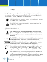
Page 32: ...structions to avoid personal injury or damage to the meter This WARNING symbol indicates a potentially hazardous situation which if not avoided could result in death or serious injury This CAUTION symbol indicates a potentially hazardous situation which if not avoided may result damage to the product This symbol advises the user that the terminal s so marked must not be connected to a circuit poin...

Page 33: ...r between terminals or between any terminal and earth ground Do no apply more than the rated voltage as marked on the multimeter between terminals or between any terminal and earth ground Only replace the blown fuse with the proper rating as specified in this manual Use caution with voltages above 30 VAC RMS 42 VAC peak or 60 VDC These voltages pose a shock hazard To avoid false readings that can ...

Page 34: ... input jack exceeds 1000 V above earth ground Never connect the meter leads across a voltage source while the func tion switch is in the current resistance or diode mode Doing so can damage the meter Function Maximum input VDC or VAC 1000 VDC DC RMS mA AC DC 800 mA 1000 V fast acting fuse AAC DC 10 A 1000 V fast acting fuse 20 A for 30 seconds max every 15 minutes Frequency resistance capacitance ...

Page 35: ...is equipment for connection to circuits in which measures are taken to limit the transient overvoltages to an appropriate low level Examples include protected electronic circuits Overvoltage category II Equipment of OVERVOLTAGE CATEGORY II is energy consuming equipment to be supplied from the fixed installation Examples include household office and laboratory appliances Overvoltage category III Eq...

Page 36: ...rrent AC DC Frequency Resistance Duty cycle Temperature C F Features True RMS Current measurement 20 A AC DC Capacity Continuity diodetest IP 67 waterproof Min max hold Automatic power off Backlight Resolution 6 000d Overvoltage category CAT III 1000 V CAT IV 600 V Inspection Once your new digital multimeter has been unpacked from the original packaging you should have the following items 1 Digita...

Page 37: ...ensor 6 Manual Front panel 1 6000 count LCD display 2 Hz button 3 RANGE button 4 MODE button 5 Function switch 6 mA μA and 10A input jacks 7 COM input jack 8 Positive input jack 9 Backlight and Hold button 10 MAX MIN button 11 REL button Tilt stand and battery compartment are on rear of unit ...

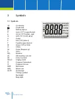
Page 38: ... 10 6 amps cap m milli 10 3 volt amp A Amps k kilo 103 ohms F Farads capacitance M mega 106 ohms Ω Ohms Hz Hertz frequency V Volts REL Relative AC Alternating current DC Direct current HOLD Display hold ºF Degrees Fahrenheit ºC Degrees Celcius MAX Maximum MIN Minimum AUTO Autorange Timing symbol Backlight Bargraph ...

Page 39: ...d Change to a higher range 4 1 DC voltage measurements CAUTION Do not measure DC voltages if a motor on the circuit is being switched ON or OFF Large voltage surges may occur that can damage the meter 1 Set the function switch to the green VDC position 2 Insert the black test lead banana plug Into the negative COM jack 3 Insert the red test lead banana plug into the positive V jack 4 Touch the bla...

Page 40: ... present CAUTION Do not measure AC voltages if a motor on the circuit is being switched ON or OFF Large voltage surges may occur that can damage the meter 1 Set the function switch to the green VAC Hz position 2 Insert the black test lead banana plug into the negative COM jack 3 Insert red test lead banana plug into the positive V jack 4 Touch the black test probe tip to the neutral side of the ci...

Page 41: ... up to 600mA DC set the function switch to the mA position and insert the red test lead banana plug into the µA mA jack 4 For current measurements up to 20A DC set the function switch to the 10A HZ position and insert the red test lead banana plug into the 10A jack 5 Press the MODE button to indicate DC on the display 6 Remove power from the circuit under test then open up the circuit at the point...

Page 42: ...na plug into the µA mA jack 4 For current measurements up to 20A AC set the function switch to the 10A HZ position and insert the red test lead banana plug into the 10 A jack 5 Press the MODE button to indicate AC on the display 6 Remove power from the circuit under test then open up the circuit at the point where you wish to measure current 7 Touch the black test probe tip to the neutral side of ...

Page 43: ...ction switch to the green position 2 Insert the black test lead banana plug into the negative COM jack 3 Insert the red test lead banana plug into the positive Ω jack 4 Press the MODE button to indicate Ω on the display 5 Touch the test probe tips across the circuit or part under test 6 It is best to disconnect one side of the part under test so the rest of the circuit will not interfere with the ...

Page 44: ...tion 2 Insert the black lead banana plug into the negative COM jack 3 Insert the red test lead banana plug into the positive Ω jack 4 Press the MODE button to indicate and Ω on the display 5 Touch the test probe tips to the circuit or wire you wish to check 6 If the resistance is less than approximately 35Ω the audible signal will sound 7 If the circuit is open the display will indicate OL ...

Page 45: ...k and the red test lead banana plug into the positive V jack 3 Press the MODE button to indicate and V on the display 4 Touch the test probes to the diode under test 5 Forward voltage will typically indicate 0 400 to 0 700 V 6 Reverse voltage will indicate OL 7 Shorted devices will indicate near 0V and an open device will indicate OL in both polarities ...

Page 46: ...e temperature probe head to the part whose temperature you wish to measure 5 Keep the probe touching the part under test until the reading stabilizes about 30 seconds 6 Read the temperature in the display Note The temperature probe is fitted with a type K mini connector A mini connector to banana connector adaptor is supplied for connection to the input banana jacks Note The temperature range of t...

Page 47: ...y function switch to the green Ω CAP position 2 Insert the black test lead banana plug into the negative COM jack 3 Insert the red test lead banana plug into the positive V jack 4 Press the MODE button to indicate nF on the display 5 Touch the test leads to the capacitor to be tested 6 The test may take up to 3 minutes or more for large capacitors to charge 7 Wait until the readings settle before ...

Page 48: ... display 5 Functions 5 1 Auto manual range When the meter is first turned on it automatically goes into Autoranging This automatically selects the best range for the measurements being made and is generally the best mode for most measurements For measurement si tuations requiring that a range be manually selected perform the following 1 Press the RANGE key the AUTO display indicator will turn off ...

Page 49: ...ading and will update only when a new min occurs 6 To exit MAX MIN mode press and hold the MAX MIN key for 2 seconds 5 3 RELATIVE mode The relative measurement feature allows you to make measurements relative to a stored reference value A reference voltage current etc can be stored and measurements made in comparison to that value The displayed value is the difference between the reference value a...

Page 50: ... feature hold down the MODE button and turn the meter on 5 7 Low battery indication The icon will appear in the lower left conner of the display when the battery voltage becomes low Replace the battery when this appears 6 Maintenance WARNING To avoid electric shock disconnect the test leads from any source of voltage before removing the back cover or the battery or fuse covers WARNING To avoid ele...

Page 51: ...eak batteries so they do not leak and damage the unit 6 If the meter is to be stored for a long period of time the batteries should be removed to prevent damage to the unit 6 1 Battery installation WARNING To avoid electric shock disconnect the test leads from any source of voltage before removing the battery cover 1 Turn power off and disconnect the test leads from the meter 2 Open the rear batte...

Page 52: ...Remove the protective rubber holster 3 Remove the battery cover two B screws and the battery 4 Remove the six A screws securing the rear cover 5 Gently remove the old fuse and install the new fuse into the holder 6 Always use a fuse of the proper size and value 0 8 A 1000 V fast blow for the 600 mA range SIBA 70 172 40 10 A 1000 V fast blow for the 20 A range SIBA 50 199 06 7 Replace and secure th...

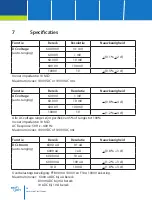
Page 53: ...00 V 1 mV 0 8 4 d 60 00 V 10 mV 600 0 V 100 mV 1000 V 1 V 1 2 4 d All AC voltage ranges are specified from 5 of range to 100 of range Input Impedance 10 MΩ AC Response 50 Hz 400 Hz Maximum Input 1000 VDC or 1000 VAC rms Function Range Resolution Accuracy DC current auto ranging 600 0 uA 0 1 uA 0 8 3 d 6000 uA 1 uA 60 00 mA 10 uA 600 0 mA 100 uA 1 2 3 d 10 A 10 mA 1 8 3 d Overload protection FF800 ...

Page 54: ...50 Hz 400 Hz Maximum input 6000 uASC rms on uA 800 mAAC rms on mA 10 AAC rms on 10 A range Function Range Resolution Accuracy Resistance Ω auto ranging 600 0 Ω 0 1 Ω 0 5 4 d 6 00 KΩ 1 Ω 60 00 KΩ 10 Ω 0 5 2 d 600 0 KΩ 100Ω 6 000 MΩ 1 KΩ 1 5 8 d 60 00 MΩ 10 KΩ Input protection 1000 VDC or 1000 VAC rms Function Range Resolution Accuracy Capacitance auto ranging 40 00 nF 10 pF 5 0 20 d 400 0 nF 0 1 nF...

Page 55: ...solution Accuracy Duty cycle 0 1 99 9 0 1 1 2 2 d Pulse width 100 us 100 ms Frequency width 5 Hz 150 kHz Sensitivity 0 5 V RMS Overload protection 1000 VDC or AC rms Function Range Resolution Accuracy Temperature 20 o C 400 o C 0 1 o C 3 0 5 o C 400 o C 1000 o C 1 o C 4 o F 752 o F 0 1 o F 3 0 8 o F 752 o F 1832 o F 0 1 o C Sensor Type K thermocouple Overload protection 1000VDC or AC rms Function ...

Page 56: ...True RMS ACV bandwidth 50 Hz 1000 Hz Crest factor 3 at full scale up to 500 V decreasing linearly to 1 5 at 1000 V Display 60 00 count backlit liquid crystal with bargraph Overrange indication OL is displayed Auto Power OFf 15 min approx with disable function Polarity Automatic no indication for positive minus sign for negative Measurement rate 2 times per second nominal Low battery indication is ...

Page 57: ...n use and protected against the users by double insulation per EN61010 1 to Category IV 600 V and Category III 1000V Pollution Degree 2 The meter also meets UL 61010 1 2 Edition 2004 CAN CSA C22 2 No 61010 1 2 Edition 2004 and UL 61010B 2 031 1 Edition 2003 Warranty Wabtec Netherlands B V guarantees the tester for a period of 12 months The period of warranty will be effective at the day of deliver...

Page 58: ...58 www nieaf smitt com ...

Page 59: ...59 www nieaf smitt com ...

Page 60: ...60 www nieaf smitt com ...

Reviews: