www.prolight.co.uk
DTM Series
User Manual
5
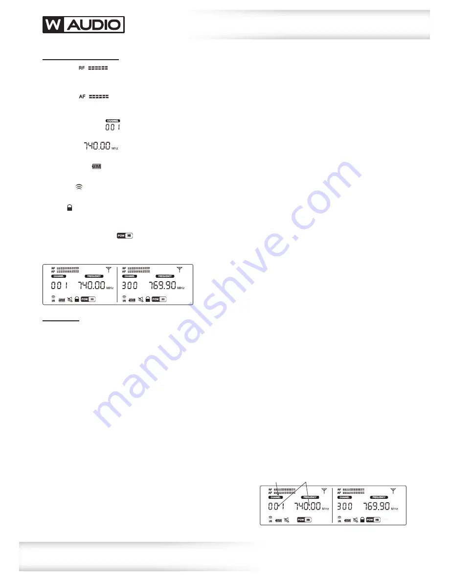
Display Identification:
1. RF Level
The RF level indicator is a visual representation of the radio frequency signal strength utilising a 10 segment bar graph.
As the radio signal received is reduced, the bar graph will reduce.
2. AF Level
The AF level indicator is a visual representation of the audio signal strength utilising a 10 segment bar graph.
As the audio signal fluctuates bar graph will indicate this.
3. Channel indicator
Displays the current RF channel in use by the transmitter/receiver.
4. Frequency
Displays the current RF frequency in use by the transmitter/receiver.
5. Battery Level
The receiver displays the current battery level in the transmitters allowing remote monitoring of the transmitters battery level.
6. IR Sync
During synchronisation, the IR Sync will flash a radiating symbol.
7. Lock
The receiver features a lock function to prevent accidental changes to the settings. Press and hold LOCK to unlock the menu
system. After a short period of inactivity, the display will automatically lock.
8. Hi/Lo transmit power
The user may select the RF transmission power from the menu system. When used in close proximity, the transmitters should
be set to Lo or over greater distances, set to Hi.
Operating instructions
Operation:
•
Carefully, lift the antennae into the vertical position.
•
Connect the included power supply to a suitable 240V AC~50Hz mains voltage outlet and plug the DC connector
into the DC. Power Input on the rear panel of the receiver (9V DC, 1500mA minimum).
•
Using the supplied audio cable, connect the MIX OUT on the rear panel of the receiver for both audio channels
to the mixer’s audio line input. The receiver also features balanced XLR outputs, one for each channel.
•
Switch on the power to the receiver, checking the display backlight illuminates.
•
Open the battery compartment on the transmitter (Beltpack – slide downwards away from the belt clip. Handheld - unscrew
the lower portion). Install the appropriate batteries into the transmitter, taking care to observe the orientation and polarity.
Only use high quality, alkaline type batteries. Refit the battery compartment cover carefully.
•
Switch on the transmitter, when switched on the display on the transmitter will illuminate.
If the display does illuminate or glows dimly, the battery will require replacement.
•
Adjust the volume on the front panel of the receiver for each of the channels.
•
Follow the IR Sync Operation fully to ensure the transmitters are linked correctly to the receiver unit.
Failure to follow this fully will prevent the microphone system from operating correctly.
•
Channel (Frequency) Setup:
Press and hold the SET button to unlock the menu function.
The CHANNEL mode will flash, use the UP/DOWN buttons to select
the desired channel, the frequency will automatically change. The DTM
800 has 20 available channels within the 863-865Mhz range, where
as the DTM 600 has 80 available within the 606-614Mhz range.
After changing the channel, the IR sync must be carried out to ensure
the transmitter is matched for correct operation.
flashes
changes


