background image

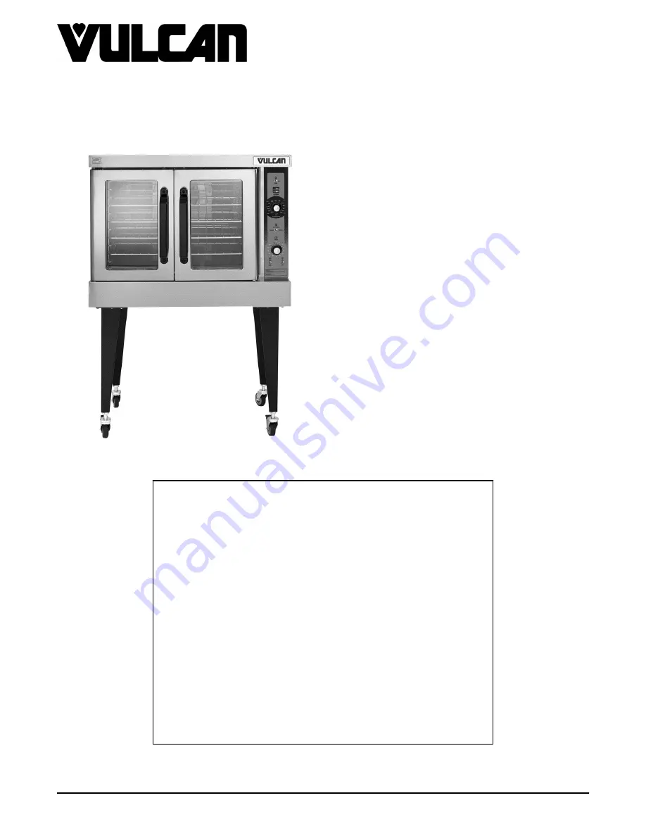
SG SERIES GAS CONVECTION
OVENS

MODELS

SG4
SG6

STACKED
MODELS

SG44

SG66

- NOTICE -

This  Manual  is  prepared  for  the  use  of  trained  Vulcan  Service
Technicians  and  should  not  be  used  by  those  not  properly
qualified.

This manual is not intended to be all encompassing. If you have
not attended a Vulcan Service School for this product, you should
read, in its entirety, the repair procedure you wish to perform to
determine if you have the necessary tools, instruments and skills
required to perform the procedure. Procedures for which you do
not  have  the  necessary  tools,  instruments  and  skills  should  be
performed by a trained Vulcan Service Technician.

The  reproduction,  transfer,  sale  or  other  use  of  this  Manual,
without the express written consent of Vulcan, is prohibited.

This manual has been provided to you by ITW Food Equipment
Group LLC ("ITW FEG") without charge and remains the property
of ITW FEG, and by accepting this manual you agree that you will
return it to ITW FEG promptly upon its request for such return at
any time in the future.

SERVICE MANUAL

A product of Vulcan-Hart

3600 North Point Blvd Baltimore, MD 21222

F45525 (0814)

Summary of Contents for SG4

Page 1: ...kills required to perform the procedure Procedures for which you do not have the necessary tools instruments and skills should be performed by a trained Vulcan Service Technician The reproduction transfer sale or other use of this Manual without the express written consent of Vulcan is prohibited This manual has been provided to you by ITW Food Equipment Group LLC ITW FEG without charge and remain...

Page 2: ...PENDENT DOORS 13 DOOR WINDOW 13 DOOR SWITCH 14 HIGH LIMIT THERMOSTAT 14 INTERIOR LIGHTS 15 COOLING FAN 15 SERVICE PRODCEDURES AND ADJUSTMENTS 17 SOLID STATE TEMPERATURE CONTROL CALIBRATION 17 SOLID STATE TEMPERATURE CONTROL TEST 18 TEMPERATURE PROBE TEST 18 GAS VALVE PRESSURE CHECK 19 VERIFICATION OF SPARK AT IGNITOR 19 DOOR SWITCH ADJUSTMENT 20 BLOWER ADJUSTMENT 20 DOOR ADJUSTMENT 21 DOOR STRIKE ...

Page 3: ... and Operation Manual for specific cleaning instructions LUBRICATION Cavity blower motor has sealed bearings and requires no additional lubrication Huskey s TF1000 grease or equivalent high temperature Teflon grease SPECIFICATIONS Electrical Voltage 120 60 1 Amps 9 0 Amps Input BTU Rating Natural Gas 60 000 BTU input at 3 5 in W C Propane Gas 60 000 BTU input at 10 0 in W C Gas Line Pressures Natu...

Page 4: ...ews on the right side which secure the control panel then pull the panel away from the oven Fig 3 NOTE If the oven has a mechanical KX type thermostat it must be removed from the control panel first before removing the control panel 2 Disconnect the temperature probe leads from the solid state temperature control 3 Unplug the wire harness connector to the control panel components 4 Reverse the pro...

Page 5: ...NTS Disconnect the electrical power to the machine and follow lockout tagout procedures Removable Components Procedure 1 Remove the as outlined RIGHT SIDE PANEL NOTE If right side panel is not accessible this component can be serviced by removing the CONTROL PANEL 2 Disconnect the wire leads to the component being replaced 3 Remove the component 4 Reverse the procedure to install the replacement c...

Page 6: ...through the oven wall and into the control panel area Fig 8 NOTE The hole in the oven cavity wall does not line up straight with the oven cavity outer shell therefore the probe must be removed at an angle 6 Reverse the procedure to install the replacement probe 7 Adjust the temperature control as outlined under SOLID STATE TEMPERATURE CONTROL CALIBRATION GAS BURNER Disconnect the electrical power ...

Page 7: ... the burner chamber 7 Check for proper operation GAS ORIFICE Disconnect the electrical power to the machine and follow lockout tagout procedures SHUT OFF THE GAS BEFORE SERVICING THE UNIT 1 Remove the BOTTOM FRONT COVER 2 Remove the bolts securing the gas manifold to the oven and place the manifold to the side Fig 13 3 Remove the gas orifice from the spud on the manifold and replace with the corre...

Page 8: ...ol Panel and the RIGHT SIDE PANEL NOTE If is right side panel not accessible this component can be serviced by removing the CONTROL PANEL 2 Disconnect the lead wires 3 Disconnect the compression fittings to the valve Fig 15 4 Loosen the bolts securing the valve and bracket assembly then remove the screws securing the valve to the bracket Fig 16 5 Verify new gas valve is configured for the proper g...

Page 9: ...ical power to the machine and follow lockout tagout procedures SHUT OFF THE GAS BEFORE SERVICING THE UNIT 1 Remove the RIGHT SIDE PANEL NOTE If right side panel is not accessible this component can be serviced by removing the CONTROL PANEL 2 Loosen the screws securing the mounting bracket to the component panel and remove the bracket Fig 20 3 Disconnect the lead wires and igniter cable from the ig...

Page 10: ...y Fig 22 3 Reverse the procedure to install the assembly and check for proper operation NOTE Check to ensure the spark gap distance is approximately 1 8 If the gap appears to be excessive or poor sparking is occurring then adjust Fig 23 BLOWER AND MOTOR Disconnect the electrical power to the machine and follow lockout tagout procedures SHUT OFF THE GAS BEFORE SERVICING THE UNIT 1 Take out the rack...

Page 11: ...face from any damage during motor assembly removal 8 Pull the motor assembly into the oven cavity and place it on the cardboard 9 Remove the junction box cover from the motor disconnect lead wires and remove the conduit 10 Remove motor mounting bolts and flat washers then lift the motor from the mounting plate 11 Position the replacement motor on the motor mounting plate and install mounting bolts...

Page 12: ...ever Fig 29 3 Remove the lower door seal strip to expose the mounting screws of the door assembly 4 Remove the two 2 lower sill bolts by the lower door shaft and the four 4 counter sunk screws from the lower sill Fig 30 NOTE The door assembly is heavy and will drop down once the last screw is removed If removing door assembly with out assistance the ignition cable flame sense lead and gas manifold...

Page 13: ...f door Fig 33 2 Independent doors A Remove the door handle then remove the outer door panel B Lift out the inner door panel and window assembly NOTE Left door only remove door seal from the inside edge of the door 3 Simultaneous doors A If replacing window on the left door remove the handle from the front of the door then remove door seal from the inside edge of the door 1 Lift out the inner door ...

Page 14: ...h and check for proper adjustment as outlined under DOOR SWITCH ADJUSTMENT HIGH LIMIT THERMOSTAT Disconnect the electrical power to the machine and follow lockout tagout procedures 1 Take out racks from the oven 2 Remove the high limit thermostat cover mounting plate from inside the oven cavity at the top Fig 36 3 Disconnect lead wires from high limit thermostat then remove high limit thermostat f...

Page 15: ...bs 2 places on the socket Fig 39 3 Depress the retaining tabs and pull the socket out from the oven far enough to disconnect the lead wires 4 Remove the socket from the oven 5 Attach the lead wires to the replacement socket 6 Insert the socket into the hole in the oven and push until the socket is held in place by the retaining tabs 7 Install the light bulb and lens 8 Check for proper operation CO...

Page 16: ... NOTE The fan must be installed so air is pulled from the rear of the oven and blown into the control area The arrow on the fan body indicates air flow direction and should be pointing toward the controls NOTE Ensure fan is seated squarely against the air tube and the oven bottom NOTE The air deflector should be angled upwards at approximately 30 degrees to properly direct the air flow SG SERIES G...

Page 17: ...eck the temperature probe as outlined under TEMPERATURE PROBE TEST b If the probe is functioning properly then temperature control is malfunctioning a Install a replacement temperature control and check calibration 8 Calculate the average temperature by adding the temperature indicated when the lamp goes out to the temperature indicated when the lamp comes on and dividing this answer by 2 Temp lam...

Page 18: ...rnal relay 1 If input voltage to the internal relay is correct proceed to Step 8 If input voltage to the internal relay is not present problem is not with the temperature control See TROUBLESHOOTING 2 If output voltage from the internal relay is correct proceed to Step 8 If output voltage from the internal relay is not correct check temperature probe as outlined under TEMPERATURE PROBE TEST 8 Set ...

Page 19: ...ced by removing the CONTROL PANEL 3 Remove the plug from the manifold pressure port Fig 42 4 Install hose barb adapter and attach manometer tube 5 Turn gas supply to the oven back on 6 Plug the unit in and turn the power switch ON 7 Set the temperature control to its highest setting and allow burner to ignite NOTE The burner must be lit during test NOTE Accurate gas pressure readings can only be m...

Page 20: ...oven frame should be observed DOOR SWITCH ADJUSTMENT Disconnect the electrical power to the machine and follow lockout tagout procedures 1 Remove the Top Front Cover 2 Door operation A Independent doors The switch actuator should be operated by the switch lever when the right door is between 1 and 1 from being closed B Simultaneous doors The switch actuator should be operated by the switch lever w...

Page 21: ... shims between motor and frame Fig 46 4 Reverse the procedure to install DOOR ADJUSTMENT Disconnect the electrical power to the machine and follow lockout tagout procedures 1 Check the doors to make sure they have an equal gap between them and that the vertical edge of the door is parallel to the vertical door seal If the doors are not positioned in this manner adjust the doors as described Fig 47...

Page 22: ...s necessary loosen fasteners close doors and insure contact between door inner surface and upper horizontal seal Slide door strike plate until contact with roller latch is made Tighten strike plate fasteners Fig 49 3 Open and close the doors several times while observing the roller latch and strike plate operation A Replace roller latch if malfunctioning as outlined under ROLLER LATCH ASSEMBLY IND...

Page 23: ...on cycle Energizes the 2nd valve main on the dual solenoid gas valve generates spark for burner ignition monitors the presence of a flame and controls the No Ignition light The ignition times are 4 second self diagnostic test initial power ON 7 second ignition trial 3 ignition trials with a 15 second purge between each trial Igniter Flame Sense Ignites the gas and senses the presence of a flame Th...

Page 24: ...COMPONENT LOCATION Fig 50 SG SERIES GAS CONVECTION OVENS ELECTRICAL OPERATION F45525 0814 Page 24 of 31 ...

Page 25: ... SG4 SG6 Solid State Temperature Control Schematic diagram AI3691 will be used to explain the electrical sequence of operation Normal Cycle 1 Conditions SG SERIES GAS CONVECTION OVENS ELECTRICAL OPERATION Page 25 of 31 F45525 0814 ...

Page 26: ...the door switch contacts and connects power to additional components when the door switch contacts are CLOSED door closed 1 Transformer T1 energized a Power 24VAC to one side of the following components heat relay R3 normally open N O contacts high limit connected through the normally closed N C contacts to the 1st valve safety on the dual solenoid gas valve a 1st valve safety on the gas valve ene...

Page 27: ...eds to be lowered C Doors are open 1 Door switch contacts OPEN D Cook timer in the OFF position 2 Power Switch S1 turned to COOL DOWN NOTE With door switch contacts OPEN doors open the convection fan motor will still run and continue to cool the oven However power would be removed from the following components Power ON light goes out transformer T1 de energized and to the component cooling fan A P...

Page 28: ...SCHEMATICS Fig 52 WIRING DIAGRAM See Wiring Diagram AI3692 SG SERIES GAS CONVECTION OVENS ELECTRICAL OPERATION F45525 0814 Page 28 of 31 ...

Page 29: ...d to the machine Exercise extreme caution at all times and follow Arc Flash procedures If test points are not easily accessible disconnect power and follow Lockout Tagout procedures attach test equipment and reapply power to test ALL MODELS SG SERIES GAS CONVECTION OVENS TROUBLESHOOTING Page 29 of 31 F45525 0814 ...

Page 30: ...function 7 Ignition Module malfunction Sparks but gas does not ignite 1 Gas solenoid valve OFF or inoperative 2 Manual gas valve CLOSED 3 Gas supply OFF or Insufficient gas pressure 4 Interconnecting wiring malfunction 5 Ignition Module malfunction Gas ignites but will not maintain flame 1 Igniter lead connections malfunction 2 Ignitor ground inoperative 3 Ignitor flame sense malfunction 4 Insuffi...

Page 31: ...t vent plugged or obstructed C Snorkel Vent plugged or obstructed 3 Air flow Baffles missing or damaged Intermittent problems 1 High ambient temperatures 2 Wiring connections loose 3 Cooling fan malfunction No power to temperature control 1 Power switch S1 in Cool Down 2 Door or door switch open SG SERIES GAS CONVECTION OVENS TROUBLESHOOTING Page 31 of 31 F45525 0814 ...

Reviews: