background image

 ERA & EBD SERIES ELECTRIC FRYERS - REMOVAL AND REPLACEMENT OF PARTS

REMOVAL AND REPLACEMENT OF PARTS

COVERS AND PANELS

Electrical Components Access Panel

1.

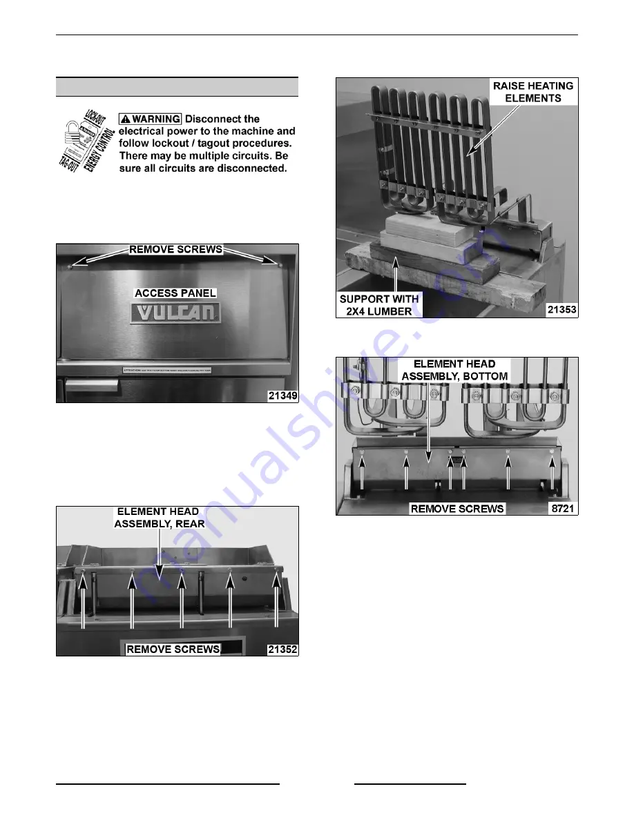
Remove screws at top of access panel and
lower panel.

2.

Lift from hinge then remove panel. 

3.

Reverse procedure to install.

Element Head Cover

1.

Drain shortening from fry tank.

2.

Remove screws from rear of element head
assembly.

3.

Raise heating elements and place 2x4 lumber
under them for support.

4.

Remove screws from the bottom of element
head assembly.

5.

Grasp heating elements and remove 2x4
lumber. Lift the elements and pull toward rear of
fryer. Head cover will separate from element
head base.

A.

Lower the heating elements and place
them in fry tank.

NOTE

: Heating elements remain attached to

element head cover.

6.

Reverse procedure to install.

F25385 (May 2010)

Page 5 of  32

Summary of Contents for 136730

Page 1: ...nt Group LLC ITW FEG without charge and remains the property of ITW FEG and by accepting this manual you agree that you will return it to ITW FEG promptly upon its request for such return at any time in the future 2ER50AF KLEENSCREEN FRYER BATTERY SERVICE MANUAL ERA EBD SERIES ELECTRIC FRYERS WITH KLEENSCREEN PLUS FILTRATION SYSTEMS MODEL ML MODEL ML 1ER50A 136730 2XER50AF 136747 1E50BD 136730 2XE...

Page 2: ...TMENTS 13 Temperature Probe Test 13 Cooking Control Calibration 14 Lift Assist Spring Adjustment 14 Heating Element Test 16 ELECTRICAL OPERATION 17 Component Function 17 Component Location 19 Sequence of Operation 20 Filtering System 20 Schematic Diagrams 22 208V 240V Fryers Shown With KleenScreen Filtration System 22 480V Fryers Shown With KleenScreen Filtration System 23 Wiring Diagrams 24 208V ...

Page 3: ...ith the Filter Ready option installed use the Mobile Filter For service information related to the Mobile filter refer to F24599 MOBILE FILTERS A GRO Frymate dump station can be configured in a battery with fryers 15 1 2 inches or 21 inches in width Model KILOWATT EACH FRY TANK FRYER WIDTH INCHES TOTAL SYSTEM SHORTENING CAPACITY LBS EACH FRY TANK 1ER50A 1E50BD 17 15 5 50 1ER50AF 1E50BDF 17 15 5 50...

Page 4: ...of the sections SPECIFICATIONS MODEL KW PER FRYER SECTION AMPS EACH FRYER SECTION 3 PHASE 60HZ PER LINE 208V 240V 480V ALL 50 LB CAPACITY FRYERS 14 39 34 17 17 47 41 20 ALL 85 LB CAPACITY FRYERS 24 67 58 29 NOTES Amperage values in the table are nominal Tolerance is 5 10 Single Floor Model Fryers 208VAC 240VAC or 480VAC 3 phase 60HZ to power the heating elements Drawer Filter System Separate elect...

Page 5: ... from fry tank 2 Remove screws from rear of element head assembly 3 Raise heating elements and place 2x4 lumber under them for support 4 Remove screws from the bottom of element head assembly 5 Grasp heating elements and remove 2x4 lumber Lift the elements and pull toward rear of fryer Head cover will separate from element head base A Lower the heating elements and place them in fry tank NOTE Heat...

Page 6: ...dure to install and check for proper operation DISCARD VALVE SWITCH KLEENSCREEN FRYERS ONLY 1 Open the door to the fryer section being serviced 2 Disconnect lead wire connector 3 Remove switch mounting screws 4 Remove discard valve switch 5 Reverse procedure to install and check for proper operation NOTE Switches are not adjustable TEMPERATURE PROBE Do not sharply bend and kink or clamp down on th...

Page 7: ...S HIGH LIMIT THERMOSTAT Do not sharply bend and kink or clamp down on the capillary tube or damage may occur 1 Raise heating elements 2 Loosen clamps securing capillary tube and bulb to element 3 Remove element head cover as outlined under COVERS AND PANELS 4 Remove high limit from mounting bracket 5 Disconnect high limit lead wires 6 Remove grommet from the element head assembly 7 Remove the bulb...

Page 8: ...e to install the replacement component and check for proper operation CIRCUIT BREAKER SUPPLY BOX COMPONENTS 1 Remove screw and circuit breaker supply box cover 2 Disconnect lead wires then remove the component being replaced NOTE Supply box will contain a circuit breaker on 24kW 208 240V units 3 Reverse procedure to install the replacement component and check for proper operation F25385 May 2010 P...

Page 9: ...ccur 1 Raise heating elements A If replacing left heating element loosen high limit bulb and capillary tube clamps Remove high limit bulb and capillary tube from clamps then position away from element B If replacing right heating element remove temperature probe clamps and position temperature probe away from element NOTE When installing high limit route the capillary tube and center the bulb betw...

Page 10: ...l eye bolt mounting nuts to release tension on springs 3 Remove lift assist springs from the eye bolt hooks 4 Remove lift assist springs from the hangers 5 To install springs A Attach spring hook to hanger thru rear door opening B Attach spring hook to eye bolt and tighten eye bolt mounting nut C Remove 2x4 lumber and lower heating elements 6 Adjust spring tension as outlined under LIFT ASSIST SPR...

Page 11: ...NT VIEW SHOWN ELEMENTS RAISED TILT SWITCH 1 Remove element head cover as outlined under COVERS AND PANELS 2 Lower heating elements 3 Disconnect lead wires from tilt switch 4 Remove tilt switch from element head 5 Reverse procedure to install and check for proper operation F25385 May 2010 Page 11 of 32 ...

Page 12: ...r tank assembly and push the tank support arms back into place under the fryer 4 Remove splash guard from base frame 5 Disconnect pump motor lead wire connector 6 From underneath the fryer A Disconnect flexible line fittings from pump 7 Remove pump motor assembly from fryer A Remove pipe fittings from the pump and install on replacement pump 8 Reverse procedure to install and check for proper oper...

Page 13: ...cycled or problem resolved A temperature probe fault can be caused by a lead wire break or a lead short To Check 1 Turn power switch off 2 Disconnect cooking control connector 3 Test the probe using a VOM to measure resistance Connect the meter leads to pins 4 5 on the male connector A If the measured resistance values are within the allowable range the probe is functioning properly Reverse proced...

Page 14: ... average temperature reading is within tolerance cooking control is properly calibrated B If the average temperature reading is out of tolerance loosen set screw to remove temperature knob and adjust calibration potentiometer NOTE Ensure that the shaft and knob position does not change when loosening set screw and removing temperature knob as this could affect calibration 1 Adjust calibration pote...

Page 15: ...en stop nut on all eye bolts 5 Adjust eye bolt mounting nuts as necessary but equally on all springs to achieve the best spring tension to hold elements in place 6 Perform spring tension check step 2 above 7 Repeat spring tension adjustment if necessary 8 Tighten stop nut on all eye bolts F25385 May 2010 Page 15 of 32 ...

Page 16: ...l to call for heat 4 Measure voltage at heating element connections and verify against data plate voltage A If voltage is incorrect see ALL MODELS under TROUBLESHOOTING B If voltage is correct check current draw amps through the heating element lead wires See table for proper values NOTE This method is preferred over a resistance check when a clamp on type amp meter is available 1 If current draw ...

Page 17: ... resistance which is monitored by the cooking control The probe is an RTD resistance temperature device of the Thermistor type As temperature increases the resistance value decreases Drain Valve Interlock Switch DVI A magnetic reed switch mounted on the manual drain valve that supplies a drain valve position signal open closed to the cooking control When drain valve is open the drain interlock inp...

Page 18: ...en filled from the filter process Filter Switch Energizes pump motor to filter the shortening when switch is closed valve handle extended Filter power switch must be turned on Discard Valve Switch A magnetic reed switch mounted on the mechanical discard valve that closes when discard valve handle is extended to discard the shortening Prevents R4 solenoid relay N C contacts from suppling power to t...

Page 19: ...ERA EBD SERIES ELECTRIC FRYERS ELECTRICAL OPERATION COMPONENT LOCATION CONTROL PANEL COMPONENTS COOKING CONTROL COMPONENTS F25385 May 2010 Page 19 of 32 ...

Page 20: ...condition occurs A If shortening reaches 460EF the high limit thermostat opens 1CON and 3CON are de energized and power is removed from heating elements 1 1CON and 3CON remain de energized until the shortening temperature drops below 460 F manual reset button is pressed and start button is actuated Filtering System The discard valve handle is connected to a mechanical valve and switch assembly to ...

Page 21: ...acted 1 Discard valve switch N O contacts open Mechanical discard valve closed 2 Turn power switch on to the fryer section to be drained 3 Set cooking control between 300 F minimum and 350 F maximum NOTE Shortening should not be drained outside of this temperature range At lower temperatures the shortening is thicker which may increase draining time and place a greater load on the pump At higher s...

Page 22: ...ERA EBD SERIES ELECTRIC FRYERS ELECTRICAL OPERATION SCHEMATIC DIAGRAMS 208V 240V Fryers Shown With KleenScreen Filtration System F25385 May 2010 Page 22 of 32 ...

Page 23: ...ERA EBD SERIES ELECTRIC FRYERS ELECTRICAL OPERATION 480V Fryers Shown With KleenScreen Filtration System F25385 May 2010 Page 23 of 32 ...

Page 24: ...ERA EBD SERIES ELECTRIC FRYERS ELECTRICAL OPERATION WIRING DIAGRAMS 208V 240V 14 17 kW Fryers Shown With KleenScreen Filtration System F25385 May 2010 Page 24 of 32 ...

Page 25: ...ERA EBD SERIES ELECTRIC FRYERS ELECTRICAL OPERATION F25385 May 2010 Page 25 of 32 ...

Page 26: ...ERA EBD SERIES ELECTRIC FRYERS ELECTRICAL OPERATION 208V 240V 24 kW Fryers Shown With KleenScreen Filtration System F25385 May 2010 Page 26 of 32 ...

Page 27: ...ERA EBD SERIES ELECTRIC FRYERS ELECTRICAL OPERATION F25385 May 2010 Page 27 of 32 ...

Page 28: ...ERA EBD SERIES ELECTRIC FRYERS ELECTRICAL OPERATION 480V Fryers Shown With KleenScreen Filtration System F25385 May 2010 Page 28 of 32 ...

Page 29: ...ERA EBD SERIES ELECTRIC FRYERS ELECTRICAL OPERATION F25385 May 2010 Page 29 of 32 ...

Page 30: ...ERA EBD SERIES ELECTRIC FRYERS ELECTRICAL OPERATION Frymate Dump Station F25385 May 2010 Page 30 of 32 ...

Page 31: ... inoperative 5 R2 power relay malfunction 6 Drain valve switch open or switch malfunction 7 Interconnecting wiring malfunction Excessive time to melt solid shortening more than 45 minutes 1 Melt cycle timing incorrect 2 Incorrect supply voltage 3 Temperature probe malfunction 4 Cooking control malfunction Excessive or low heat 1 Incorrect supply voltage 2 Temperature probe malfunction 3 Contactor ...

Page 32: ...ing shortening in the line to drain into the filter tank to prevent possible clogging after the shortening cools and solidifies Close the filter drawer when complete 3 Shortening below 300 F to thick 4 Discard valve switch malfunction N O contacts not closing to energize R3 filter relay coil 5 R3 fill relay malfunction contacts remain closed NOTE The fill solenoid valve should not be energized dur...

Reviews: