7
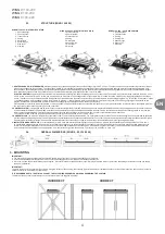
3.2.2. VERTICAL INSTALLATION USING INSTALLATION BRACKETS.
It is possible to install WING to a wall vertically on both sides of the gate (with the motor on the bottom or on the top).
For this option it is not important if you screw the handles down to the unit first and then screw the whole down to the wall or first attach the handles to the wall and then screw the curtain down to the
handles.
To install the curtain vertically, use 1/4-UNC x 2 3/4 (outside the scope of VTS delivery) screws. Screw 2 or 3 brackets using the screws, passing through flat washers (3), to the threaded sleeves mounted
in the upper part of the housing.
IMPORTANT:
For vertical installation, keep minimum distance of 4 inches between the floor and the lower end of the curtain. This is to secure free access to the water coil air vent.
E
IMPORTANT!
The device is intended for the operation in dry rooms, exclusively. Thus, pay particular attention to the condensation of water vapor on engine elements, since it is not fitted
for operating in humid environment.
IMPORTANT!
The WING air curtains are not intended for the installation:
●
Outdoor.
●
In humid rooms;
●
In rooms categorized as explosive environments.
●
In rooms with very high levels of dustiness;
●
In rooms with aggressive atmosphere (due to the presence of copper and aluminum structural elements in the heat exchanger and electric heaters).
IMPORTANT!
The WING EH air curtains are not intended for the installation on suspended ceilings.
3.3. INSTALLATION GUIDELINES
CONNECTION OF THE HEATING MEDIUM
When connecting the air curtain to the heating water pipeline, secure the coil headers from excessive torque using set of two keys. The weight of installed pipelines should not impose a load on
the
heater’s
headers.
IMPORTANT!
Pay particular attention to the leak-tightness of connections, when filing the hydraulic system. Make sure that the water flowing from a leaky connection does not leak to the
electric engine (at the vertical installation)
IMPORTANT!
It is recommended to use filters in the hydraulic system. It is recommended to clean/rinse the system, draining a few liters of water, prior to the connecting of hydraulic conduits
(the supply conduits, in particular).
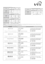
EXAMPLE OF HYDRAULIC SYSTEM
1. WING 100-200
2. VALVE WITH ACTUATOR
3. VENT VALVE
4. SHUT-OFF VALVE
5. FILTER
6. CIRCULATING PUMP
7. BOILER
1
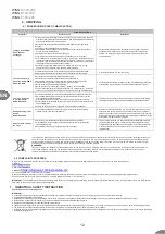
VENTING OF DEVICE/DRAINING OF HEATING MEDIUM
To perform horizontal and vertical installation, the exchanger on the right-hand side of the door vents automatically. In the case of horizontal installation with the stub pipes facing downwards, to
vent the exchanger, remove the side cover. Unscrew the screws (1) around the cover and remove the cover. A valve with a hose is situated below the cover.
RE
T
UR
N
S
UP
P
LY
S
UP
P
LY
RE
T
UR
N
m
in
.
4
in
EN
Summary of Contents for WING C100-200
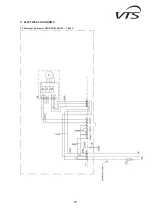
Page 15: ...15 9 ELECTRICAL DIAGRAMS 9 1 Electrical diagram of WING W100 200 EC 1 240V ...
Page 17: ...17 9 3 Electrical diagram of WING E100 EC 1 240V ...
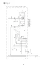
Page 18: ...WING W100 200 WING E100 200 WING C100 200 18 9 4 Electrical diagram of WING E100 EC 3 240V ...
Page 19: ...19 9 5 Electrical diagram of WING E100 EC 3 480V ...
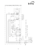
Page 21: ...21 9 7 Electrical diagram of WING E150 200 EC 3 480V ...


