background image


trigger voltage is applied the amplifier will power up if the rear rocker switch is in the ON position, and 
when the hold is released, the amplifier automatically powers down. 

In all cases the front panel power button takes precedence to power down. If the amplifier is powered on via 
the front panel button then applying the trigger voltage will not cause a change. If either the trigger voltage is 
released or the front panel power button is pressed the amplifier powers down. If the trigger voltage is left 
on, but the power button is pressed then the amplifier will power down, and will stay off unless the trigger 
voltage is cycled down and then back up. 


Mute Trigger 

The amplifier can be toggled between the muted and unmated modes while it is in power on mode by using the Mute 
Trigger. 


Mode Trigger 

The amplifier can be toggled between the triode and tetrode modes while it is in power on mode by using the Mode 
Trigger. 

MB-450 Series III Signature Monoblock  Owner’s Manual 
 

28 


Summary of Contents for MB-450 Series III

Page 1: ...VTL MB 450 Series III Signature Monoblock Amplifier Owner sManual ...

Page 2: ...ny form or by any means electronic or mechanical for any purpose without the express written permission by VTL Version History Version 1 0 September 30 2010 Part Number OM MB 450 III Copyright 2010 by VTL Amplifiers Inc All rights reserved 4774 Murrieta Street Suite 10 Chino CA 91710 USA Phone 909 627 5944 Fax 909 627 6988 Email mail vtl com http www vtl com MB 450 Series III Signature Monoblock O...

Page 3: ...ier at the rocker switch 17 Using the DF switches 17 DF Switch Settings 18 Fault indication 20 Tube Fault 20 1 Tube red Fault Mute LED blinking Red deck LED green 20 2 High Current TUBE Fault Mute Power Mode LEDs off deck LED green 21 3 TUBE green Fault Mute LED blinking green deck LED green 21 Power Fault Mute LED blinking fast red no deck LED lit 23 Replacing tubes 23 Resetting a Tube Red Fault ...

Page 4: ...SPECIFICATIONS 33 CHAPTER 5 34 WARRANTY 34 APPENDIX 35 Warranty Registration 35 Service Notes 35 MB 450 Series III Signature Monoblock Owner s Manual iii ...

Page 5: ... in a safe place for future reference The Origin of the MB 450 Signature Monoblock Amplifier The MB 450 Signature Monoblock Amplifier including its predecessors has been a core model in the VTL line for over 20 years With the release of the Deluxe 300 monoblocks in the late 80 s VTL successfully introduced a high power amplifier that could drive a wide range of speakers and yield outstanding perfo...

Page 6: ...and stabilize the power supplies for greater tonal stability and sonic integrity especially during complex dynamic signal conditions All critical voltages in the power supply are precision regulated for consistent and predictable performance under a wide variety of conditions Large energy storage reservoirs mean that the amplifier is capable of delivering huge peak current swings into demanding lo...

Page 7: ... Damage to the unit that is the result of improper AC connection and grounding will not be covered under the warranty Prior to connecting this amplifier to any audio or video equipment in your system make sure this unit s power and the rest of the equipment connected to its input and output channels is turned off Adding or removing input or output cables to the amplifier while the system is powere...

Page 8: ...edures described in this manual For all other service and questions please contact your authorized VTL dealer or the factory Operational Warnings It is critical for proper sonic performance of this component that it be properly configured for the mode of operation while playing If a balanced signal is applied to the inputs the amplifier must be configured for balanced operation and vice versa Alwa...

Page 9: ...ier and allow the tubes to cool down before attempting to work with the tubes Tube components can be heavy and awkward to lift with the weight unevenly distributed You should not attempt to move the unit without help The amplifier weighs approximately 120 lbs 55 Kg Use only the same type and rating of fuses as specified in the owners manual and marked on the unit Using fuses that exceed the rating...

Page 10: ...lift away the packaging and set all the packaging in the carton 5 When lifting the unit be sure to only lift it from the bottom under the transformers Be careful not to break any switches Be sure to only set the amplifier down on its bottom side on the four rubber feet on a stable surface Setting it on any other side may damage protruding components If the unit is too heavy or too awkward to lift ...

Page 11: ...e re used to fasten the cage back to the amplifier 4 Remove the left and right covers of the cage and locate the tube sockets for the output tubes on the deck of the amplifier For the MB 450 amplifier there should be a total of 8 sockets for the output tubes 4 on the left side and 4 on the right side of the cage covers 5 Insert the output tubes into each of the output tube sockets from tube 1 to 4...

Page 12: ...cket which matches Press the tube firmly into its socket using a gentle force and a slight rocking motion When the tube is properly and completely inserted into the socket it should be firmly implanted and does not give in to any movement at all when you try to rock it 5 After the output tubes are firmly located in their sockets restore the left and right top covers back onto the cage Fit the orig...

Page 13: ...hese components together 2 Connect the power amplifier to the output channel of the preamplifier The interconnect cable between the amplifier and the preamplifier links the input channel of the power amplifier to the output channel of the preamplifier The amplifier which is going to drive the left channel of your speaker system should be connected to the left output channel of the preamplifier The...

Page 14: ...ure that you can operate your power amplifier under the best conditions for the optimal results you should plug the unit directly into a wall AC outlet preferably one separate outlet for each unit Do not plug your amplifier into a light extension cord or into the back of another component This will starve the amplifier of current and significantly impact the performance of your system See the chap...

Page 15: ...he Logic supply and the top deck LEDs next to each output tube will turn on once and off in sequence to identify the tubes going from tube 1 to tube 8 If the amplifier is ready for power up within five seconds after the rocker is turned on the Mute LED on the front panel will turn on green to indicate that the amplifier is now in standby mode MB 450 Series III Signature Monoblock Owner s Manual 11...

Page 16: ...ger input labeled POWER The amplifier can be left in this mode continuously since the Logic supply draws very little power 5W If the amplifier shows a red fast flashing Mute LED then it is not ready for power up Refer to the Fault section of this manual for instructions on how to identify and clear faults From Standby Mode to Power On Mode MB 450 Series III Signature Monoblock Owner s Manual 12 ...

Page 17: ...e the Power LED turns off and the Mute LED flashes fast red then there is a fault either Red Tube or Power See the Fault section When the Power on cycle is completed the Mute LED turns off and the Power and Mode LEDs remain on If there are any low tubes that cannot be biased the Mute LED will blink slow green but the amplifier will still operate The amplifier is now ready to play music Mute and Un...

Page 18: ...ny time to toggle between the tetrode and triode modes The Mute LED lights to a steady red immediately after the Mode button is pressed and no signal will be allowed during this changeover period In the middle of this switch over sequence the user will hear a clicking sound and the color of the Mode LED will change its color to correspond to the new Mode selected The Mute LED will start blinking r...

Page 19: ...Deck and Deck LED Indications MB 450 Series III Signature Monoblock Owner s Manual 15 ...

Page 20: ...MB 450 Series III Signature Monoblock Owner s Manual 16 ...

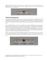
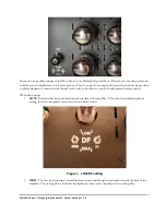
Page 21: ...e user wishes to completely turn off the amplifier turn the rocker switch in the back of the amplifier to the off position All LEDs on the front panel should be completely turned off in this mode Using the DF switches The variable DF is an adjustable Damping Factor control that allows the user to adjust the output impedance of the amplifier The two sets of DF switches are located on the deck of th...

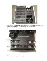
Page 22: ...er control to loudspeakers that may need it DF Switch Settings 1 LOW Both switches are positioned towards the back of the amplifier This is the lowest damping factor setting the least loudspeaker control and most natural sound Figure 1 LOW DF setting 2 MED The Left switch forward towards the front panel and the right switch back towards the back of the amplifier This setting allows for better loud...

Page 23: ...udspeaker control with a little more impact on sound quality but on speakers that need the control the sonic improvement is clear Figure 3 HI DF Setting 4 MAX Both switches forward towards the front panel This setting provides the maximum damping factor but sonic impact could be noticeable MB 450 Series III Signature Monoblock Owner s Manual 19 ...

Page 24: ...owing sections to determine which type of fault has occurred Do not turn off the rocker switch in the back of amplifier until you have determined which type of fault has occurred and the faulty tube is replaced Tube Fault 1 Tube red Fault Mute LED blinking Red deck LED green When any output tube draws excessive current and cannot be controlled by the autobias system the amplifier will shut down wi...

Page 25: ...lament might not be working or the tube could be completely out of the socket Either way the Autobias system will be unable to bring the tube up to full power This is a warning indicator only since the amplifier can continue to operate without the need to shut down immediately as balance across the output transformer is maintained with the system shutting off the corresponding tube in the push pul...

Page 26: ...sensing system to be able to operate properly a second low tube will cause the amplifier to shut down and indicate replacement of both tubes MB 450 Series III Signature Monoblock Owner s Manual 22 ...

Page 27: ...lue as indicated in the Data Specification section of this manual and re power after allowing 5 minutes to drain the power supplies If both fuses are good then refer servicing of your amplifier to your authorized VTL dealer or service technician The internal fuse could be blown and the amplifier must be returned to the VTL dealer for servicing Replacing tubes Turn off the rear rocker switch and re...

Page 28: ... Locate the two screws on the side of the left and right covers Remove these two screws with the 2 Phillips screw driver also 3 Save these screws in a safe place so that they can be re used to fasten the cage back to the amplifier 4 Remove the tube cover and put it aside in a safe place MB 450 Series III Signature Monoblock Owner s Manual 24 ...

Page 29: ...st flashing or slow blinking green LED next to one of the output tubes This is indicating that this is the faulty tube that is causing the problem 6 Replace the bad tube with a known good tube of the same type MB 450 Series III Signature Monoblock Owner s Manual 25 ...

Page 30: ...ias Fault Sensing system that the bad tube has been replaced Once the fault is cleared the amplifier will allow re power 3 Before re powering check the Plate and Screen fuses on the back of the amplifier Using a multimeter check the continuity of the Plate and Screen fuses to see if they are open If either of the fuses is open replace it with a good fuse of the same value and type as indicated in ...

Page 31: ...d tube brands that are recommended by VTL VTL specified replacement tubes are available from your authorized VTL dealer or the VTL factory service department Any damage incurred to units that use non VTL approved tubes will not be covered under the warranty Trigger functions For remote controlled convenience this amplifier offers 3 x 12V triggers to toggle the Power Mute and Mode functions that ar...

Page 32: ...ltage is released or the front panel power button is pressed the amplifier powers down If the trigger voltage is left on but the power button is pressed then the amplifier will power down and will stay off unless the trigger voltage is cycled down and then back up Mute Trigger The amplifier can be toggled between the muted and unmated modes while it is in power on mode by using the Mute Trigger Mo...

Page 33: ... that you turn off the amplifier from the rocker switch located on the back panel of the amplifier Tube Types The VTL MB 450 Series III Signature Monoblock amplifier uses a total eight 6550C tubes for the output stage and one 12AT7 and one 12BH7 tube for the input and driver stages Tube Life Your VTL amplifier has been designed to ensure long tube life Total tube life generally lasts on the averag...

Page 34: ...warranty Changing the Screen Plate Mains Logic B Input Fuses The amplifier has one Screen fuse that is rated at A fast acting 600V fuse as well as a Plate Power supply fuse rated at 2 5A fast acting 600V fuse The Mains fuse is a 15A Ceramic Slow Blow fuse for 100 120V and 7A Ceramic Slow Blow for 220 240V AC The Input and Logic fuses are both 1A Ceramic Slow Blow for 100 120V and 0 75A Ceramic Slo...

Page 35: ...into the holder pushing it downward while turning it in the clockwise direction to lock it in place Use the same procedure to replace the output stage protection fuses WARNING For continued protections against fire hazard only replace the fuse with the same type and rating as was specified for the amplifier by the VTL factory If you have problems locating the correct fuse contact your VTL dealer o...

Page 36: ...me ground potential or same AC outlet In single ended mode a ground loop hum can result from a difference in ground potential between different components in the system and it is recommended that the system be operated in the balanced mode to defeat ground loop problems Under no circumstances should you attempt to defeat the ground with a ground lifter cheater plug as serious damage to the compone...

Page 37: ...rode S N Ratio 200 W Triode 110dB 120 Hz Power Consumption Idle 300 W Full Power 1000 W Primary Mains Fuse Rating Input Fuse Logic Fuse 100 120V 15A Ceramic Slo Blo 220 240V 7A Ceramic Slo Blo 100 120V 1A Ceramic Slo Blo 220 240V 0 75A Ceramic Slo Blo 100 120V 1A Ceramic Slo Blo 220 240V 0 75A Ceramic Slo Blo B Fuse Rating Plate Fuse 2 5A fast acting 600V Screen Fuse 0 75 fast acting 600V Dimensio...

Page 38: ...sole remedy shall be to return the product to the authorized VTL dealer or to VTL Amplifiers Inc where the defect will be repaired without charge for parts and labor The product will then be returned via prepaid insured freight method and carrier to be determined solely by VTL Amplifiers Inc All returns to the factory must be in the original packing and accompanied by a Return Authorization new pa...

Page 39: ...e 10 Chino CA 91710 USA To help you keep a record of the serial number and purchase information please enter the following information into this manual Product Model Number ___________________________ Serial Number ___________________________ Purchase Date ___________________________ Authorized Dealer ___________________________ Service Notes Date Service Initials ___________ _____________________...

Reviews: