


2
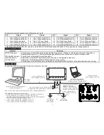
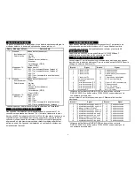
The nMAP2 access point has two radios and an integral antenna array.
The default and available operation for each radio are:
Radio
Default Mode
Other Choices*
1
Operating mode:
Access Point
Wireless mode:
802.11ac
Operating Modes:
Client
Ad-Hoc
802.11s
Pseudo Ad-Hoc (ahdemo)
Monitor
Access Point (WDS)
Client (WDS)
Wireless modes:
802.11b (not compatible with antenna)
802.11g (not compatible with antenna)
802.11a
802.11g+n (not compatible with antenna)
802.11a+n
2
Operating mode:
Access Point
Wireless mode:
802.11g+n
Operating Modes:
Client
Ad-Hoc
802.11s
Pseudo Ad-Hoc (ahdemo)
Monitor
Access Point (WDS)
Client (WDS)
Wireless Modes:
802.11b
802.11g
802.11g+n
802.11a+n (not compatible with antenna)
802.11ac (not compatible with antenna)
* Choices may be limited by Country selected during setup.
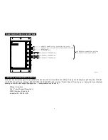
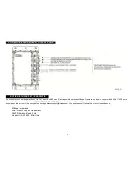
Reset lines are available in connector J1. Momentary connection of
pins 13 and 14 reboots the nMAP2 access point (WLAN1 and WLAN2
indicators flash in unison, one flash per second for approximately one
minute). Holding connection until WLAN1 and WLAN2 indicators flash
alternately at one flash per second resets the nMAP2 to the factory
default settings. Reset lines are not connected in aircraft installation.
Two discrete inputs accessed via connector J1 enable remote on/off
(power supply enable) and RF on/RF off (RF enable) control. Inputs
must be connected to signal ground to power up and enable RF.
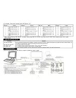
The nMAP2 access point has three auto sensing 10/100/1000 Base-T
Ethernet ports accessed via connectors J2 and J3.
Connector J1 provides connection for input power, discrete signals, and
IP address selection. (See nMAP2 Operator’s Manual M365-769 for IP
address selection wiring.)
Pin*
Signal
Pin*
Signal
1
IP Strap 0
11
No connection
2
IP Strap 1
12
No connection
3
IP Strap 2
13
Reset (not used on aircraft)
4
IP Strap 3
14
Signal Ground
5
Power Supply Enable
15
28 VDC Positive (Primary)
6
IP Strap 0 Ground
16
115 VAC Line (Hot)
7
IP Strap 1 Ground
17
No connection
8
IP Strap 2 Ground
18
115 VAC Neutral
9
IP Strap 3 Ground
19
Chassis Ground
10
RF Enable
20
28 VDC Return
* Use Deutsch shell DMC-MD 20A, insert & contacts DMC M 20-22SN,
backshell 787-8055-13M or equivalent for mating connector.
Connector J2 provides connection for Ethernet port 2 and power out.
Pin*
Signal
Pin*
Signal
1
Port 2 Bidirectional Pair A+
11
No connection
2
Port 2 Bidirectional Pair B+
12
No connection
3
Port 2 A/B Inner Shield
13
No connection
4
Port 2 Bidirectional Pair C+
14
No connection
5
Port 2 Bidirectional Pair D+
15
No connection
6
Port 2 Bidirectional Pair B-
16
No connection
7
Port 2 Bidirectional Pair A-
17
No connection
8
Port 2 C/D Inner Shield
18
No connection
9
Port 2 Bidirectional Pair D-
19
No connection
10
Port 2 Bidirectional Pair C-
20
No connection
* Use Deutsch shell DMC-MD 20B, insert & contacts DMC-M 20-22PN,
backshell 787-8055-13M or equivalent for mating connector.
RADIOS AND ANTENNAS
DISCRETE INPUTS
INTERFACE CONNECTORS
RESET OPERATION
ETHERNET PORTS


