background image

11

Sensor Design

2  Sensor Design

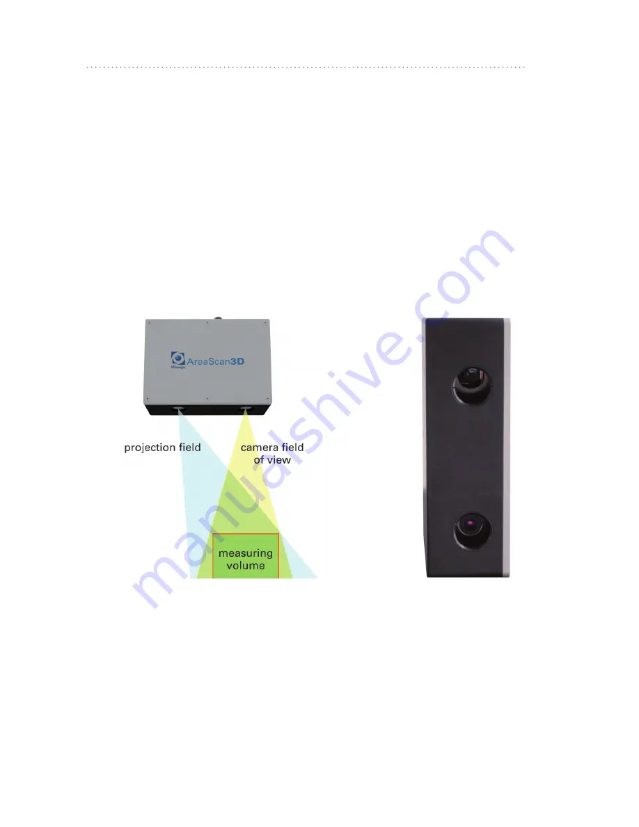
Projection unit, camera and signal processing components are en-

closed in a protective housing conforming to IP65. 
Projector and camera each work through a protective glass window.
The viewing angle of the camera is perpendicular to the case. The 

fringe projector has a slanted adjustment and throws its light into the 

camera‘s field of view. Therefore, an exact working distance is re-

quired.

projector

camera

Fig. 7: Sensor design

Summary of Contents for AreaScan3D

Page 1: ...AreaScan3D Manual ...

Page 2: ...ic AreaScan3D sensor Subject to technical changes The document is protected by copyright All rights reserved No part of this documentation may be reproduced or transmitted for any purpose in any form or by any means electronically or mechanically without expressly written permission ...

Page 3: ......

Page 4: ...trical Installation 14 4 1 Connections and Indicators 14 4 2 Connecting the Sensor 15 5 Operation 17 5 1 Measuring Field Requirements 17 5 2 Positioning the Sensor 18 5 3 Positioning the Measured Object 19 6 Software API 21 7 Technical Specifications 22 7 1 Type specific data 22 7 2 General data 23 7 3 Conformity to Standards 23 8 Troubleshooting 24 8 1 Hardware 24 8 2 Errors in 3D Image 25 ...

Page 5: ... measurement offering the following highlights Optical 3D sensor based on digital fringe projection Metric calibrated measuring data Export formats 3D point cloud or height encoding gray level image GenICam transport layer compatible Interfaces to Common Vision Blox HALCON Aluminum case IP65 conforming M12 standard industrial connectors 24V operation Ethernet ...

Page 6: ...the package are complete 1 3 Intended Use The VRmagic AreaScan3D is an area sensor The device is intended to provide three dimensional measurements of surfaces of a certain area and depth from a predefined distance The field of application is industrial image processing The measurements are transmitted via an Industrial Ethernet interface as ready to use 3D data sets 1 4 Type Label Fig 1 Type Labe...

Page 7: ...tripes are projected onto an object A camera sees the fring es from a different angle The perspective deformation of the fringes seen encodes the 3D coordinates of object points along the fringes With this basic principle alone the distance resolution would depend on the camera resolution and the triangulation angle Fig 2 Triangulation ...

Page 8: ...ne shaped brightness modulation These stripes can be quite wide as their position can be determined at high accu racy from the gray levels of the stripe flanks The distance resolution here is no longer dependent on the camera resolution Distance reso lution can be measured more than 10 times more accurate compared to mere triangulation ...

Page 9: ... iden tify the single fringes In order to assign each fringe seen to a proper distance range a sequence of binary patterns is projected Black and white patterns of stripes with varying width are used for this see following figure The sequence of brightness values results in a binary number which di rectly represents the stripe number This number also indicates which particular stripe in the phase ...

Page 10: ...ing mirrors are arranged on a chip Digital Micromirror Device DMD These micro mirrors can switch positions within microseconds by electrostatic force Gray levels are generated by varying the on off times This results in digital precision The DMD is the main component of the projector DLP projectors Digital Light Processing offer high efficiency low temperature drift and extreme durability the mech...

Page 11: ...conforming to IP65 Projector and camera each work through a protective glass window The viewing angle of the camera is perpendicular to the case The fringe projector has a slanted adjustment and throws its light into the camera s field of view Therefore an exact working distance is re quired projector camera Fig 7 Sensor design ...

Page 12: ...ons on page 22 Mounting the AreaScan3D 1 Decide in which position the AreaScan3D is to be mounted orien tation distance to the measured surface see Technical Specifica tions on page 22 2 Vibrations can disturb the measuring process substantially If necessary use vibration absorbing components for mounting the sensor 3 Pencil 6 mounting holes onto the mounting surface The distance of the hole cente...

Page 13: ...13 Mounting Fig 8 Dimensions and mounting holes ...

Page 14: ... 2 24 V 18 30 V DC ripple 2 V Pin 3 4 GND Input Output M12 A coding 8 pin connector Pin 1 Output 0 24 V 100 mA Pin 2 4 5 6 GND Pin 3 Input 0 24 V Pin 7 reserved Pin 8 reserved 100 MBit Ethernet M12 D coding 4 pin connector Pinout according to Industrial Ethernet standard Status LED green LED off no power supply also possible directly after connecting LED flashes sensor is booting duration approx 1...

Page 15: ...nnections and indicators 4 2 Connecting the Sensor Fig 10 Communications block scheme The sensor is controlled by the network LAN connection only Any number of sensors can be connected to a network also via switches or routers similar to PCs and other network enabled devices ...

Page 16: ...D to an existing network or PC using an adequate Industrial Ethernet cable see Connections and Indicators on page 14 2 The I O lines Input Output one each can be configured for various functions via the software e g the input as a trigger for starting a measurement 3 Connect the AreaScan3D to a suitable power supply ð ð After a short time the status LED starts flashing The sensor is not ready for ...

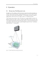
Page 17: ...r This defines a certain distance range and a certain common field of view or measuring area The measuring volume of the 3D sensor is roughly determined by its lateral length and width and by a depth range that lies around the opti mal measuring distance see following figure These parameters have to be taken into account when positioning the sensor see Technical Specifications on page 22 Fig 11 Th...

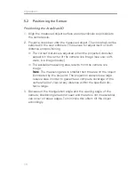
Page 18: ...r of the camera live image see user soft ware live image display ð ð The available measuring area results from the camera live image Note The measuring area is smaller than the area on the object illuminated by the projector The projection always has a large reserve area in order to guarantee a complete coverage of the camera field of view at any distance within the specified dis tance range 3 Bec...

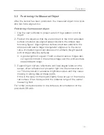
Page 19: ...f shadowing and can also result in artifacts height peaks with strongly reflective surfaces ð ð A good alignment is given if both wide and narrow fringes deli ver a good contrast in the camera image over the entire surface area and depth range 3 Depending on surface reflectance and local angles relative to the sensor direct reflections of projector light into the camera can oc cur This may result ...

Page 20: ...20 Operation Fig 12 Example for good alignment ...

Page 21: ...21 Software API 6 Software API Refer to the separate software documentation on the provided USB flash drive ...

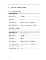
Page 22: ...orking distance 257 5 1 mm from lower case edge Min projection time time the object has to stand still 0 5 s 3D data calculation period 2 s AreaScan3D 01 120 Measuring volume 120 x 75 x 50 mm Measuring points 748 x 480 Micro mirrors 480 x 320 Point density 160 µm Height resolution 20 µm Working distance 285 5 mm from lower case edge Min working distance 260 5 mm from lower case edge Max working di...

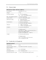
Page 23: ...e transport Altitude 0 3050 m operating 0 13000 m storage transport Vibration to be avoided operating storage transport sine 5 g 10 500 Hz all main axes acc to DIN EN ISO 9022 36 08 0 random 0 015 g2 Hz 5 1000 Hz Impact to be avoided operating storage transport 15 g 11 ms half sine all main axes max 3 impacts per axis 7 3 Conformity to Standards Applied standards Case sealing IP65 Optical emission...

Page 24: ...ure the voltage at the plug Sensor does not work Reset not successful Remove power cable for 10 seconds then reconnect Green LED permanent ly blinking more than approx 1 minute after applying power Reset not successful Remove power cable for 10 seconds then reconnect Communication pro blem with PC e g sensor not found I O problem Software See software docu mentation Also check network cable ...

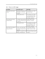
Page 25: ...d of view see software manual 3D image has strong height peaks At abrupt area boundari es some overshooting is normal Apply filtering see software manual Strong reflections Turn object use other viewing angle or limit the field of view see software manual 3D image has ripples in fringe direction Environment light has changed during measu rement Avoid light changes shield excessive light Object or ...

Page 26: ......

Page 27: ......

Page 28: ...VRmagic GmbH Augustaanlage 32 68165 Mannheim Germany Phone 49 621 400 416 0 Fax 49 621 400 416 99 info imaging vrmagic com www vrmagic imaging com 2013 VRmagic GmbH Mannheim ...

Reviews: