background image


TOUGH CAM 

Version 1.0 


Model: WVOS7MDCL1Q 


PLEASE READ CAREFULLY AND SAVE 

This manual contains important information about this product’s operation.     

If you are installing this product for others, you must have this manual – or a copy –   

with the end user.

Summary of Contents for WVOS7MDCL1Q

Page 1: ... Model WVOS7MDCL1Q PLEASE READ CAREFULLY AND SAVE This manual contains important information about this product s operation If you are installing this product for others you must have this manual or a copy with the end user ...

Page 2: ...RTANT SAFETY PRECAUTIONS Damages caused by non compliance with this operating manual will void the warranty We will not assume any liability for damages to items or persons caused by improper handling or non compliance with the safety notices Any warranty claim will be null and void in such cases 1 Do not drop puncture or disassemble the camera otherwise the warranty will be voided 2 Avoid all con...

Page 3: ...the following measures Reorient or relocate the receiving antenna Move the equipment away from the receiver Plug the equipment into an outlet on a circuit different from that to which the receiver is connected Consult the dealer or an experienced radio television technician for additional suggestions You are cautioned that any change or modifications to the equipment not expressly approved by the ...

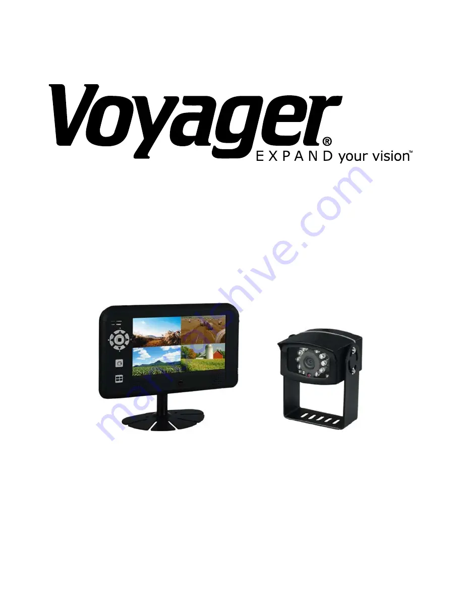
Page 4: ...5dBi antennas 2 EA 9 5 ft cable and mounting bracket 2 EA Wireless 7 LCD monitor 1 EA Monitor mount 1 EA Remote control for the monitor 1 EA Cigarette adaptor for the monitor 1 EA Hardwire cable for monitor screw bag x 1 DC power cable x 1 trigger cable x1 1 EA User s Manual 1 EA ...

Page 5: ... with horseshoe joints to the power source 12 24V Connect the red cable to the positive pole and the black cable to the negative pole Note If you are not sure which is the positive or negative pole please try one way and switch the cables if it doesn t work Mixing up the positive and negative poles won t damage the camera 4 Start the vehicle engine to power up the camera The power indicator will b...

Page 6: ...o the monitor 3 Turn on the monitor and shift the gear to Reverse 4 The screen should show the image of the car rear view automatically If it doesn t please refer to the Pairing Camera s section to pair the camera with the monitor Note It is strongly recommended to keep the system in QVGA mode with better FPS to ensure smooth images STOP BACKING when NO SIGNAL shows on the monitor With battery pac...

Page 7: ...ntenna on the antenna connector 2 Secure stand base to stand with provided screws 3 Fix the mounting metal panel to the back panel of monitor 4 Secure stand to mounting metal panel adjust proper view angle and secure the joint with T bolt ...

Page 8: ...e package 6 Connect the cigarette adaptor to the DC power jack of the LCD monitor 7 Plug the power unit to the cigarette power source beside the driver s seat and turn on the ignition and press the Power button to turn on the monitor 8 Stand the receiver antenna upright to have the best reception ...

Page 9: ...GETTING TO KNOW YOUR CAMERA 1 Camera Lens 2 Pairing Key 3 Mounting Bracket 4 IR LEDs 5 EDS 6 Antenna 7 Power cord to the vehicle back light 8 Link LED Indicator 9 Power LED Indicator ...

Page 10: ...GETTING TO KNOW YOUR RECEIVER Power Button Link Indicator Power Indicator Antenna Socket Trigger Cable Power Adaptor ...

Page 11: ... Mode Cursor Left QUAD View Mode Hot key CH4 5 Menu Mode Menu Enter Button 6 SCAN Mode SCAN Button 7 QUAD Mode QUAD Button Monitor Display Icons Signal Indicator shows signal strength as below Indicator Signal Level Zero Low Fair Good Perfect Channel Indicator shows your current active camera Status Indicator appears when the monitor receives no signal Signal Indicator Channel Indicator Status Ind...

Page 12: ...the scan frequency You can configure the system to perform scanning every 3 seconds 8 seconds 15 seconds Camera setting CAM 1 4 Turn ON OFF the specified camera or set to Mirror to mirror the camera image If the camera is set OFF the camera image won t show on the monitor even it is supplied with power 1 Press MENU button and to choose CAM 1 2 Press to turn ON OFF CAMERA 1 or MIRROR the camera ima...

Page 13: ...rce Please refer to the With battery pack section and follow the instruction in the Installing the Camera chapter to install the camera properly Example If you want to pair a new camera to channel 3 please follow the steps below 1 Press MENU button to choose the channel 3 in the Pair CAM function and start the pairing process 2 System will count down within 60 seconds system message as shown 3 Wit...

Page 14: ... Brightness function 2 Press MENU button to enter the sub menu 3 Use to choose the monitor or camera 1 4 and press to adjust the brightness 4 Choose EXIT and press MENU button to return to the main menu Monitor and Camera Version Use this feature to check the monitor and camera version number when it is necessary If you need to check the monitor and camera version number press MENU button and to c...

Page 15: ... The camera images will be displayed periodly in scan mode Unavailable channel will be displayed as blank screen To leave SCAN display please press Left Right Up Down to go to the specified channel Setting QUAD Display Press the QUAD button to enter the QUAD mode and display all the camera images on the monitor 1 Press MENU button and use Left Right to turn all available channels ON 2 Press QUAD b...

Page 16: ...re setting QUAD display make sure all cameras are paired to assigned channels Please refer to the Pair CAM section for instruction QUAD display will be restored to one camera display every time after your press directional keys for manual scan 2 To display properly TURN ON all available channels PRIOR to entering into QUAD mode Note In QUAD display the Camera Pairing function is not available ...

Page 17: ...button See Advanced Operation Pairing Camera section as a guide Low signal or unstable signal Antenna directional limitation Adjust camera antenna and receiver position Strong radio signal near by Keep WIFI router away from the camera and or receiver Backing camera image is missing during manual scan Scan channel s been set OFF Press OK button go to menu enable the channel s See Advance Operation ...

Page 18: ...2 2 480GHZ Modulation GFSK Transmission Power 20 dBm extension cable antenna Communication distance 200M Power Source Power Supply DC 12 24V Current Consumption IR ON 220mA IR OFF 150mA Waterproof IPxx IP66 Monitor LCD Panel Size 7 0 Resolution 480 234 Luminance 200cd Back Light LED Transceiver Frequency 2 405 2 480GHZ Modulation GFSK Sensitivity 82DBm TV Format NTSC PAL Video Compression MJPEG Re...

Page 19: ......

Page 20: ......

Page 21: ...ial installation This equipment generates uses and can radiate radio frequenc y energy and if not installed and used in accordance with the in structions may cause harmful interference to radio communications However there is no guarantee that interference will not occur in a particular insta llation If this equipment does cause harmful interference to radio or television reception which can be de...

Reviews: