


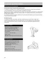


Step 5
8
Assembly Instructions
a.
Attach the Left Elbow Pad (
7
),Right Elbow Pad (
6
)and Elbow Pad Rubber Bushing (
46
) onto the
Handle Frame (
2
).Adjust to your desired position and fix using M6 Knob(
6
) and φ18×φ6.5×R29×1.5mm
Arc Washer.
b.
Attach the Handle Frame (
2
) onto the Handle Support Frame (
3
). Adjust to your desired position and
fix using 1 x 20mm L–Shaped Lock Knob (
28
) and 1 x U-Shaped handle locking bracket (
10
) (Which was
pre-fitted inside of the Handle support frame (
3
).
To Tighten:
Turn 20mm L–Shaped Lock Knob (
28
) handle clockwise, then pull the handle upward and
turn anticlockwise to the starting position, repeat above operation to tighten the lock knob.
To Loosen:
Turn 20mm L–Shaped Lock Knob (
28
) handle anticlockwise, then pull the handle upward
and turn clockwise to starting position. Repeat above operation to loose the lock knob.
Summary of Contents for V-V700
Page 24: ...Exploded Parts Diagram 23...