VONROC MS505AC Original Instructions Manual Download Page 8

8

EN

WWW.VONROC.COM

2.  MACHINE INFORMATION

Intended use

The electro tool is intended as a stationary machine 

for making straight lengthways and crossways cuts 

in wood. Horizontal mitre angles of -45° to +45° as 

well as vertical bevel angles of -45°  are possible.


This saw is intended for sawing wood only. 

Do not use the saw to cut materials other 

than wood.  

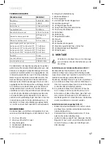
TECHNICAL SPECIFICATIONS

Model No.

MS505AC

Mains voltage

220-240V~, 50Hz

Capacity

1500W

Machine class

II (double insulated)

No load speed

4.500/min

Saw blade measurement

216 x 30 x 2.8mm

Angle for mitring

45° (left and right)

Angle for bevelling

45° (only left)

Mitre saw maximum sawing
capacity:
 

Mitre 0° - Bevel 0°


Mitre 0° - Bevel 45°


Mitre 45° - Bevel 0°


Mitre 45° - Bevel 45°

70 x 305mm
35 x 305mm
70 x 210mm
35 x 210mm

Weight

12 kg

Lpa (sound pressure)

93.6+3 dB(A)

Lwa (acoustic capacity)

106.6+3 dB(A)

The declared noise emission value(s) have been 

measured in accordance with a standard test 

method and may be used for comparing one tool 

with another. The declared noise emission value(s) 

may also be used in a preliminary assessment of 

exposure. The noise emissions during actual use of 

the power tool can differ from the declared values 

depending on the ways in which the tool is used 

especially what kind of workpiece is processed. 

Need to identify safety measures to protect the op-

erator that are based on an estimation of exposure 

in the actual conditions of use (taking account of 

all parts of the operating cycle such as the times 

when the tool is switched off and when it is running 

idle in addition to the trigger time).
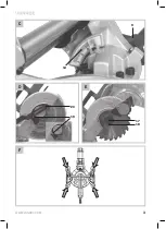
DESCRIPTION

The numbers in the text refer to the diagrams on 

page 2-3.

1.   On/off switch

2.  On/off switch for laser

3.   Lock-off button

4.   Carbon brush cover

5.   Lock-pin

6.   Blade protective cover

7.   Workpiece clamp

8.   Guide fence

9.   Knob adjusting saw angle

10. Locking knob

11. Locking paddle

12. Knob over sliding support

13. Connection dust bag

14. Bevel angle

16. Cover

17. Saw blade bolt

18. Flange

19. Screw

20. Screw retraction arm

21. Extension pieces (left and right)

22. Lock-button saw blade

23. Angle indicator

3. ASSEMBLY

Before carrying out any work on the 

machine, disconnect the mains plug from 

the power supply.

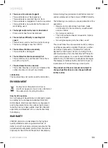
Install of a stationary machine (Fig. F)

This machine is a stationary machine and for safety 

reasons must always be firmly installed and not 

used for mobile applications.

You can install the machine in two ways: 

a)   As a stationary machine on a workbench.  

In case the machine must be secured to the 

workbench with 4 bolts.

b)   As a stationary machine on a sub frame. In this 

case the machine must be secured to the sub 

frame with 4 bolts and the sub frame anchored 

with 4 bolts to the floor plate with dimensions 

of at least 1 square meter.

Installation of the mitre saw (Fig. B)

•   Place one sidebar (21) on the right-hand side of 

the machine and the other sidebar on the left-

hand side of the machine.

Summary of Contents for MS505AC

Page 1: ...SLIDING MITRE SAW MS505AC EN Original Instructions 04 DE Übersetzung Der Originalbetriebsanleitung 12 ...

Page 2: ...WWW VONROC COM 2 A B 3 14 5 10 23 22 4 1 3 1 2 8 7 11 10 13 16 6 12 21 9 ...

Page 3: ...WWW VONROC COM 3 C F 14 9 D 20 19 E 17 18 ...

Page 4: ...ust be pulled outward when sawing mitre bevel angles Ø30mm Ømax 216mm Take note of the dimensions of the saw blade The hole diameter must fit the tool spindle without play If it is necessary to use reducers ensure that the dimensions of the reducer are suitable for the base blade thickness and the saw blade hole diameter as well as the tool spindle diameter Wherever possible use the reducers provi...

Page 5: ...Dress properly Do not wear loose clothing or jewellery Keep your hair and clothing away from moving parts Loose clothes jewellery or long hair can be caught in moving parts g If devices are provided for the connection of dust extraction and collection facilities ensure these are connected and properly used Use of dust collection can reduce dust related hazards h Do not let familiarity gained from ...

Page 6: ...pect your workpiece before cutting If the workpiece is bowed or warped clamp it with the outside bowed face toward the fence Always make certain that there is no gap between the workpiece fence and table along the line of the cut Bent or warped workpieces can twist or shift and may cause binding on the spinning saw blade while cutting There should be no nails or foreign objects in the workpiece Do...

Page 7: ... not touch the saw blade after working before it has cooled The saw blade becomes very hot while working Never make warning signs on the machine unrecognisable If laser radiation hits your eye you must close your eyes and immediately turn your head away from the beam Do not use any optical instruments such as binoculars to view the radiation source Doing so can damage your eye Do not direct the la...

Page 8: ...hat are based on an estimation of exposure in the actual conditions of use taking account of all parts of the operating cycle such as the times when the tool is switched off and when it is running idle in addition to the trigger time DESCRIPTION The numbers in the text refer to the diagrams on page 2 3 1 On off switch 2 On off switch for laser 3 Lock off button 4 Carbon brush cover 5 Lock pin 6 Bl...

Page 9: ...ng in a clockwise direction Remove the Flange 18 and the saw blade Replace the saw blade making sure that the arrow marked on the saw blade must point in the same direction as the arrow shown marked on the ma chine The saw blade teeth must point downwards Fix the saw blade bolt 17 use the saw blade lock button 22 in order to secure tightly Lower the blade cover 6 in order for the bolt cover to fal...

Page 10: ...ing the saw make sure the saw is in inward position Check that all locks and tensioning devices are secure Make sure the mitre angle is set to 0 Make sure the bevel angle is set to 0 Lock the Knob adjusting saw angle 9 by turn ing it clockwise Slide the machine completely towards yourself Lock the sliding function by turning Kob over sliding support 12 clockwise Unlock the Lock pin 5 on the right ...

Page 11: ... national right power tools that are no longer usable must be collected separately and disposed of in an environmentally friendly way WARRANTY VONROC products are developed to the highest quality standards and are guaranteed free of defects in both materials and workmanship for the period lawfully stipulated starting from the date of original purchase Should the product develop any failure during ...

Page 12: ...r Laserstrahlung der Klasse 2 gemäß EN 60825 1 Diese kann dazu führen dass Personen erblinden Transportieren Sie die Maschine nur wenn sie in der Eingangstransportposition ist Gerät der Schutzklasse II schutzisoliert kein Schutzkontakt erforderlich 1 2 3 Beim Sägen von Gehrungs winkeln muss die verstellbare Anschlagschiene nach außen gezogen werden Ø30mm Ømax 216mm Beachten Sie die Abmessungen des...

Page 13: ...rmindert das Risiko eines elektrischen Schlages 3 Sicherheit von Personen a Seien Sie aufmerksam achten Sie darauf was Sie tun und gehen Sie mit Vernunft an die Arbeit mit einem Elektrowerkzeug Benutzen Sie kein Elektrowerkzeug wenn Sie müde sind oder unter dem Einfluss von Drogen Alkohol oder Medikamenten stehen Ein Moment der Unachtsamkeit beim Gebrauch des Elektrowerk zeugs kann zu ernsthaften ...

Page 14: ...e und Griffflächen erlauben keine sichere Bedienung und Kontrolle des Elektrowerkzeugs in unvorhergesehenen Situationen 5 Service a Lassen Sie Ihr Elektrowerkzeug nur von qualifi ziertem Fachpersonal und nur mit Original Er satzteilen reparieren Damit wird sichergestellt dass die Sicherheit des Elektrowerkzeugs erhalten bleibt ZUSÄTZLICHE SICHERHEITSHINWEISE Gehrungskappsägen sind zum Schneiden vo...

Page 15: ...nger als die Tischoberseite sind für eine ange messene Abstützung z B durch Tischverlänge rungen oder Sägeböcke Werkstücke die länger oder breiter als der Tisch der Gehrungskappsäge sind können kippen wenn sie nicht fest abge stützt sind Wenn ein abgeschnittenes Stück Holz oder das Werkstück kippt kann es die untere Schutzhaube anheben oder unkontrolliert vom rotierenden Blatt weggeschleudert werd...

Page 16: ...sanleitung beschriebenen Einstellmöglichkeiten können Sie gefahrlos nutzen Stehen Sie nicht in direkter Linie mit dem Sägeblatt vor dem Elektrowerkzeug Stellen Sie sich immer neben das Sägeblatt So schützen Sie Ihren Körper vor einem möglichen Rückschlag Halten Sie Hände Finger und Arme von dem rotierenden Sägeblatt fern Greifen Sie nicht mit einer Hand über die andere wenn Sie sich vor dem Werkze...

Page 17: ... weisen auf die Abbildungen auf den Seiten 2 bis 3 1 Ein Aus Schalter 2 Ein Aus Schalter für Laser 3 Einschaltsperre 4 Kohlebürstenabdeckung 5 Sicherungsstift 6 Klingenschutzabdeckung 7 Werkstückklemme 8 Führungsgitter 9 Justierknopf für den Sägewinkel 10 Arretierungsknopf 11 Verriegelungsschaufel 12 Knopf über der gleitenden Stütze 13 Anschluss Staubbeutel 14 Keilwinkel 16 Abdeckung 17 Sägeblatts...

Page 18: ...sperrknopf 22 Drehen Sie das Sägeblatt vorsichtig mit der Hand bis das Sägeblatt einrastet Verwenden Sie den Innensechskant Schrauben dreher um die Sägeblattschraube 17 durch Lösen im Uhrzeigersinn zu entfernen Entfernen Sie den Flansch 18 und das Sägeblatt Ersetzen Sie das Sägeblatt und stellen Sie sicher dass der auf dem Sägeblatt markierte Pfeil in die gleiche Richtung zeigt wie der auf der Mas...

Page 19: ...ei Druck aus Geben Sie dem Gerät Zeit das Werkstück durchzusägen Bewegen Sie das Gerät wieder vorsichtig nach oben und schalten Sie es durch Loslassen des Schalters 1 aus Nutzung der Gleitfunktion Abb A Die Maschine muss fest mit einer Werkbank verschraubt sein Verwenden Sie die Gleitfunktion um breite Werkstücke zu sägen Fixieren Sie das Werkstück mit der Klemme Lösen Sie den Knopf 12 Schieben Si...

Page 20: ...as Sägeblatt ist durch Harz oder Sägespäne verstopft Das Sägeblatt ist für das betreffende Werkstück nicht geeignet 3 Der Höhen und oder Gehrungsschnitthebel ist verstopft Späne und oder Staub müssen entfernt werden 4 Der Motor erreicht die volle Drehzahl nur schwer Das Verlängerungskabel ist zu dünn und oder zu lang Die Netzspannung beträgt weniger als 230 Volt 5 Das Gerät vibriert übermäßig Das ...

Page 21: ...Gewährleistung des Unter neh mens dar sowohl ausdrücklich als auch implizit Es gibt keine anderen ausdrücklichen oder still schweigenden Garantien die über das hier Genannte hinausgehen einschließlich der stillschweigenden Garantien der Marktgängigkeit oder Eignung für einen bestimmten Zweck In keinem Fall ist VONROC haftbar für Neben oder Folgeschäden Die Rechts mittel des Händlers beschränken si...

Page 22: ...WWW VONROC COM 22 ...

Page 23: ...5 EU of the European parliament and of the council of 8 June on the restriction of the use of certain hazardous substances in electrical and electronic equipment is in conformity and accordance with the following standards and regulations DE Der Hersteller erklärt eigenverantwortlich dass dieses Produkt der Direktive 2011 65 EU des Europäischen Parlaments und des Rats vom 8 Juni 2011 über die Eins...

Page 24: ... 2020 VONROC WWW VONROC COM 2012 30 ...

Reviews: