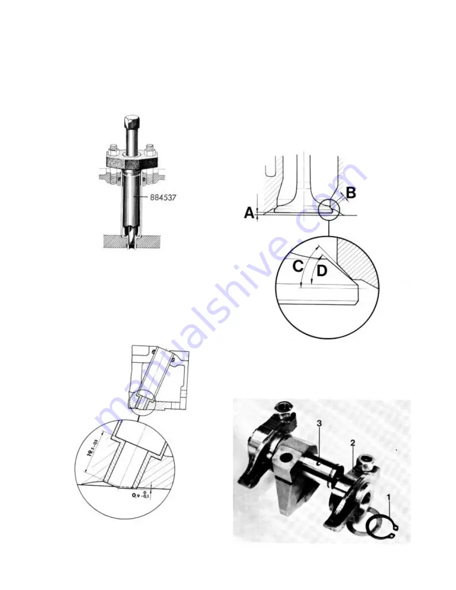
Valve and valve seat grinding
51.
Machine the valve seats by milling or grinding them.
Grind no more than is necessary to give the seat the correct
shape and a good mating surfa ce. The seat angle C shall be
45° and the width “B” approximately 1 mm (0,0394 in.). The
width is adjusted with a 39° and a 60° miller respectively or
a grinding disc. Clean the valves and grind them in a
machine. The valves’ face angle D shall be 44,5°. The
sealing surface is ground no more than is necessary to
“clean” it. If less than 1 mm (0,0394 in.) is left on the valve
edge it is to be discarded. Likewise the valve is discarded if
the valve stern is not straight or if dimension “A” exceeds 2,5
mm (0,0984 in.). Note! If this dimension is exceeded even if
a new valve is fitted, the cylinder head must be changed.
49.
Lubricate the mandrel tool 884537 and insert the tool
into the sleeve. (Ensure that the centre screw is sufficiently
unscrewed.) Place some nuts or several washers on the
studs so that the yoke can be tightened in place with the
fixing nuts. Screw in the mandrel as far as the mating face of
the sleeve allows. The mandrel is then withdrawn. Remove
the tool.
50.
Adjust the length of sleeve protruding from the cylinder
head face, (length is 0,9 mm) (0,0354 in.) and check that the
sleeve is correctly fitted (dimension 19,5 mm). (0,7677 in.).
Rocker mechanism
52.
Remove the circlip from the rocker shaft and remove the
rocker arms. Clean the parts. Be particularly careful when
cleaning the rocker shaft oil channels 3 and the rocker arm’s
oil hole, see also fig. 53.
15
Summary of Contents for MD5A
Page 1: ...Publ No 3061 Dec 1975 WORKSHOP MANUAL MD5A Marine diesel engine ENGINE UNIT ...
Page 36: ...34 ...
Page 37: ...35 ...
Page 38: ......


