background image

18

Summary of Contents for Group 655-601

Page 1: ...Service Manual Trucks Group 655 601 Rear Suspension T Ride VN VHD PV776 TSP142921 ...

Page 2: ......

Page 3: ...he following levels of observations cautions and warnings are used in this Service Documentation Note Indicates a situation handling or circumstance which should be observed Caution Indicates a potentially hazardous situation which if not avoided may result in minor or moderate injury or damage to property Warning Indicates a potentially hazardous situation which if not avoided could result in dea...

Page 4: ......

Page 5: ...ing Plate 14 Lower Reaction Rod Bracket and Shock Bracket 14 Troubleshooting 17 Rear Suspension Troubleshooting 17 Volvo T Ride 17 Service Procedures 19 Service Procedure 19 Guidelines for Working on the Volvo T Ride Suspension 19 V Torque Rod Replacement 21 Torque Radius Rod Lower Replacement 23 Bogie Anchorage Assembly Replacement 25 V Torque Rod Anchorage Replacement 28 Spring Assembly Rear Lea...

Page 6: ...2 ...

Page 7: ...uspension is designed for use in both on and off highway applications It offers maximum articulation for maximum traction The following information covers specifications operations torque values lubrication alignments and service procedures for repair and maintenance of the Volvo T Ride Tandem Suspension 3 ...

Page 8: ...4 ...

Page 9: ...3210HV RT3210HV Meritor Rockwell Axle Not Available Not Available Not Available Not Available Not Available Dana Eaton Axle Not Available Not Available Not Available Not Available Not Available Load Distribution 50 50 50 50 50 50 50 50 50 50 Springs Type Parabolic Multileaf Parabolic Multileaf Parabolic Multileaf Multileaf Multileaf Number of Leaves 3 9 3 11 3 9 11 9 11 9 11 5 ...

Page 10: ...using VOLVO Axles 140 25 103 18 Rubber spring bolts M14 to axle housing Rockwell Eaton Axles 200 30 148 22 Bottom spring plate bolts M12 to rubber spring 85 15 63 11 U bolts to torque rod bracket on axle do not re use U bolt nuts 200 25 148 18 Bracket for V Torque rod bolt nuts to frame 320 50 236 37 Axle stop bolt nuts to frame 1 140 25 103 18 Shock bracket to frame 200 30 148 22 Lower shock brac...

Page 11: ...Group 72 Specifications Axle Pinion Angles VN Axle Variant 1st Axle 2nd Axle Volvo Axle 3 11 Meritor Rockwell Axle 3 11 5 Dana Eaton Axle 3 10 7 ...

Page 12: ...8 ...

Page 13: ...337 Pry Bar can be used to remove seals bearings thrust washers and other items W6001361 Volvo Tool 998 8185 Snap Ring Pliers are used for removing and installing snap rings Note Protective eye wear should be worn when removing snap rings W6001359 Snap On Tool A173 can be used to remove the inner thrust washer and other items W6001360 9 ...

Page 14: ...535 4300 W7000250 The J 38460 A is a digital protractor available from Kent Moore Telephone 800 328 6657 W7000708 The J 38460 25 may be used along with the Kent Moore digital protractor or the Dana Spicer digital inclinometer for checking pinion angles It is available from Kent Moore Telephone 800 328 6657 W7000726 The J 36795 are tandem axle calipers available from Kent Moore Telephone 800 328 66...

Page 15: ...o the end of each spring resting on the respective rear axle These cushions absorb shock and vibration The suspension features eight torque rods that help maintain the rear axle alignment Four of the rods are installed on top of the rear axles in an opposite V pattern These V torque rods anchor the rear axles to the frame while distributing and maintaining laterally transmitted forces as well as a...

Page 16: ...ion for the suspension The spring cradle functions axially as well as radially while riding on the trunnion tube in the Bogie Bracket The axial play in the cradle is preset by the depth of the trunnion tube in the Bogie Bracket saddle The spring cradle also contains two nylon bushings which contain journals for lubricating the assembly W6001340 Nylon Bushings The nylon bushings serve as journals f...

Page 17: ...af spring assembly and contribute to a flexible and comfortable ride The rubber springs allow for minimum wear on the suspension by absorbing a considerable amount of shock and vibration for the suspension W6001343 V Stay Torque Rods The V Stay torque rods distribute movement and keep the axles in place They are fastened from the inner frame rails and to the top of the axle housings They distribut...

Page 18: ...ubber spring bracket provides a solid mounting surface for the rubber springs which is essential to the alignment of the leaf spring assembly with the rubber spring W6001337 Rubber Spring Plate The rubber spring plate is used to fasten the lower leaf spring to the rubber springs The rubber spring plate is important because it keeps the leaf springs in alignment with the rubber springs W6001342 Low...

Page 19: ...Group 72 Design and Function W6001328 Bogie Bracket and Cradle Assembly 15 ...

Page 20: ...rease Seal 16 Grease Seal 17 Nylon Bushing 19 Outer Thrust Washer 20 Inner Thrust Washer 21 Snap Ring 22 Gasket 23 Hub Cab 24 Retaining Ring 25 Relief Valve 26 Trunnion Tube 27 Roll Pin 28 Roll Pin 29 Plug 30 Plug 31 Grease Fitting Cross Section View of Cradle and Saddle Bracket 16 ...

Page 21: ...per thrust alignment Total wheel alignment incorrect Lateral alignment of axles incorrect Worn torque rod bushings Tracking Defective rubber spring 1 Improper lubrication will cause these components to fail prematurely or excessively Improper maintenance Excessively worn nylon bushings Excessive end play on cradle 1 Improper lubrication will cause these components to fail prematurely or excessivel...

Page 22: ...18 ...

Page 23: ...or easier removal or installation of T Ride Suspension components it may be necessary to remove the fifth wheel to adequately perform service procedures Refer to the appropriate service literature for removing the fifth wheel 4 To ensure that the U bolts and Torque Rods holding the rear suspension to the drive axle retain their clamp load observe the following practices Anytime you work on the sus...

Page 24: ...Group 72 Service Procedures 5 After the necessary work has been performed on the B Ride Tandem Suspension vehicle realignment may be required Refer to the proper service information 20 ...

Page 25: ...level surface and chock the front wheels 2 W7000752 Bottle jack DANGER Failure to properly support the nose of the axle may result in the axle falling which can cause serious injury or death to anyone near or under the vehicle Place a bottle jack under the axle flange to prevent the axle from rolling over 3 W6001320 Remove the four bolts that mount the V Torque Rod to the frame mounted bracket 21 ...

Page 26: ... a lifting fixture and line up the pins for proper alignment 7 Start the flange nuts on the axle mounted bracket and torque them to 310 30 Nm 229 26 ft lb 310 30 Nm 229 26 ft lb 8 Start the bolts on the frame mounted bracket and torque them to 260 30 Nm 192 22 ft lb 260 30 Nm 192 22 ft lb 9 After starting all fasteners and tightening them to the proper torques clip the electrical and pneumatic har...

Page 27: ...on a level surface and chock the front wheels 2 W7000752 Bottle jack DANGER Failure to properly support the nose of the axle may result in the axle falling which can cause serious injury or death to anyone near or under the vehicle Support the nose of the axle or axles being worked on with a bottle jack 3 Remove the lower torque rod from between the rear axle mounting bracket and the saddle bracke...

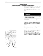
Page 28: ... W6001355 Reinstall the torque rod back onto the truck and torque the bolts to 200 25 Nm 148 18 ft lb Note It may be necessary to loosen torque rods on both sides of the suspension for easier installation 200 25 Nm 148 18 ft lb 24 ...

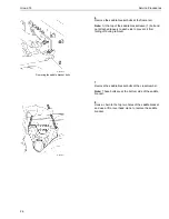
Page 29: ...ear or under the vehicle Support the nose of the axle or axles being worked on with a bottle jack 3 Please refer to Spring Assembly Rear Leaf Removal and Installation page 30 for removing the Leaf Spring Assembly 4 Please refer to Cradle Replacement page 41 for removing the Cradle Assembly 5 W6001355 Remove the 2 bolts and nuts that connect the lower torque rods to the saddle bracket Note It may b...

Page 30: ...e bracket leave 1 bolt and nut attached loosely to each side to prevent it from falling off during removal 7 Remove the saddle bracket bolts at the crossmember Note These bolts are at the bottom side of the saddle bracket 8 W6001324 Hook a chain to the top two holes of the saddle bracket and use a lift or overhead crane to remove the saddle bracket 26 ...

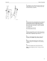
Page 31: ...M16 bolts to 320 50 Nm 236 37 ft lb to the frame and crossmember 200 30 Nm 148 22 ft lb 320 50 Nm 236 37 ft lb 11 Install the 2 bolts that connect the lower torque rods to the saddle bracket and torque For correct specifications please refer to Tightening Torques page 6 12 Refer to Cradle Replacement page 41 for service procedures for installation of the Cradle Assembly 13 Refer to Spring Assembly...

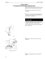
Page 32: ...re from the suspension and support it with jack stands at the front and rear of the suspension 3 W7000752 DANGER Failure to properly support the nose of the axle may result in the axle falling which can cause serious injury or death to anyone near or under the vehicle Place a bottle jack under the axle flange to prevent the axle from rolling over 4 W6001312 Removing the U bolts Remove the 4 U bolt...

Page 33: ...he saddle bracket to assist in the removal of the upper V Torque rod bracket 10 W6001323 Once all bolts are removed slide the upper V Torque rod bracket out from in between the frame and the crossmember 11 Slide the replacement upper V Torque rod bracket into place and start all bolts Torque M14 bolts to 200 30 Nm 148 22 ft lb and M16 bolts to 320 50 Nm 236 37 ft lb Note The upper V Torque rod bra...

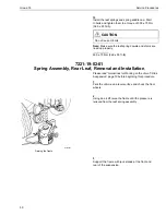
Page 34: ...Nm 369 55 ft lb 7221 19 02 01 Spring Assembly Rear Leaf Removal and Installation Please read Guidelines for Working on the Volvo T Ride Suspension page 19 before beginning this procedure 1 Park the vehicle on a level surface and chock the front wheels 2 W7000269 Raising the frame Using an air lift raise the frame until the pressure is relieved from the leaf spring assembly 3 Support the frame with...

Page 35: ... ends of the lower leaf spring 7 Using a lift or overhead crane remove the lower leaf spring and remove the U bolts Note It may be necessary to rotate the cradle back and forth to remove the U bolts 8 Install the U bolts and the lower leaf spring onto the cradle CAUTION Do not reuse U bolts Note It may be necessary to rotate the cradle back and forth to install the U bolts 9 Once the lower leaf sp...

Page 36: ...ring Leaves the leaves on both sides should be replaced When replacing the leaves also insure that the leaves are marked with the same Camber Settings or 0 11 Install the saddle cap and U bolt nuts Torque the U bolt nuts to 500 75 Nm Torque all U bolt nuts to 10 Nm before applying the full amount of torque 500 75 Nm 369 55 ft lb 12 Raise the frame and remove the jack stands then lower the frame an...

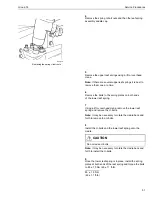
Page 37: ...cedure 1 Park the vehicle on a level surface and chock the front wheels 2 W6001333 Removing the spring end nuts Remove the nuts from the spring ends 3 Raise the frame and support the frame rails with jack stands one at the front and one at the rear of the rear suspension 4 W6001312 Removing the U bolt nuts Remove the spring U bolt nuts and then the spring saddle cap 33 ...

Page 38: ...reassembly the spring assembly Note When replacing Parabolic Spring Leaves the leaves on both sides should be replaced When replacing the leaves also insure that the leaves are marked with the same Camber Settings or 0 9 To reinstall the spring assembly reverse procedures 1 through 4 10 Torque U bolt nuts to 500 75 Nm 370 55 ft lb Torque top spring end nuts to 144 31 Nm 107 23 ft lb Torque bottom ...

Page 39: ... Ride Suspension page 19 before beginning this procedure 1 Park the vehicle on a level surface and chock the front wheels 2 W6001333 Remove the four Allen fasteners from the spring plate 3 W7000269 Raising the frame Using an air lift raise the frame to relieve pressure from the rubber spring and remove the spring plate 35 ...

Page 40: ...103 18 ft lb 140 25 Nm 103 18 ft lb 6 Lower the frame slowly while sliding the spring plate back into position 7 Once the spring plate is in position install the Allen head fasteners and torque them to 85 15 Nm 63 11 ft lb 85 15 Nm 63 11 ft lb 8 Lower the frame completely and remove the wheel chocks 9 Torque top spring end nuts to 144 31 Nm 107 23 ft lb Torque bottom spring end nuts to 260 30 Nm 1...

Page 41: ...Group 72 Service Procedures 10 Torque bolts for rubber spring to axle pads as follows VOLVO 115 25 Nm 85 18 ft lb Rockwell Eaton 73 17 Nm 54 13 ft lb 115 25 Nm 85 18 ft lb 73 17 Nm 54 13 ft lb 37 ...

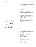
Page 42: ...hicle on a level surface and chock the front wheels 2 W6001312 Removing the U bolt nuts Remove the spring U bolt nuts and then the spring saddle cap 3 W6001314 Removing the U bolts Remove the spring U bolts 4 To facilitate the U bolt removal rotate the cradle to the left and right and slide the U bolt out CAUTION Do not reuse U bolts 5 To reassemble with new U bolts reverse procedures 1 through 3 ...

Page 43: ...Group 72 Service Procedures 6 Torque U bolt nuts to 500 75 Nm 370 55 ft lb Note It there are several upper leaf springs it is best to remove them one at a time 500 75 Nm 370 55 ft lb 39 ...

Page 44: ... washer shims that are fastened to the saddle bracket at the lower torque rod end W6001355 Fig 2 Bogie Bracket and Tandem alignment 1 To remove or install washer shims remove the long through bolts that hold both the front and the rear lower torque rod ends at the saddle bracket 2 After installing or removing shims re torque bolt nuts to 200 25 Nm 148 18 ft lb 200 25 Nm 148 18 ft lb 3 Refer to the...

Page 45: ...0269 Raising the frame Using an air lift raise the frame and support it with jack stands at the front and back of the suspension 3 W6001312 Removing the U bolts Once the frame is supported and the suspension is relieved of pressure remove the four U bolt nuts and remove the spring saddle cap 4 Using a lifting device remove the upper leaf springs Note If there are several upper leaf springs it is b...

Page 46: ...wer leaf spring to enable to removal of the lower leaf spring 6 W6001314 Remove the lower leaf spring and remove the U bolts from the cradle Note It may be necessary to rotate the cradle back and forth to remove the U bolts 7 W6001315 Remove the hub cap from the cradle and clean off the grease from around the snap ring 42 ...

Page 47: ...ent the risk of injury due to contact with sulfuric acid or explosion 9988185 9 W6001319 Removing the outer thrust washer Using VOLVO tool 9992337 remove the outer thrust washer 9992337 10 W6001317 Removing the outer thrust washer Slide the cradle off from the trunnion tube and remove the inner thrust washer Use Snap On tool number A173 to remove the inner thrust washer A173 43 ...

Page 48: ... outer thrust washer and snap ring Note It is recommended to use a new snap ring when replacing cradle seals or grease seals Make sure the snap ring is fully seated 14 Install the hub cap and torque the bolts to 20 5 Nm 15 4 ft lb 20 5 Nm 15 4 ft lb 15 Reverse the procedures steps 1 5 for installing the leaf spring assembly Torque U bolt nuts to 500 75 Nm 369 55 ft lb Torque the spring plate bolts...

Page 49: ...ves and lightly smear clean grease over grooves 3 Install new grease seals The larger of the two grease seals fits on the inside groove and the smaller one fits on the outer groove The grease seal lips face each other when in position 4 Lightly apply grease on both seals 5 Remove the wear ring from the cavity in the saddle bracket and install a new wear ring This wear ring can be removed using a f...

Page 50: ...he bearing is filled completely with grease 1 W7000264 Cradle bearing lubrication points Remove pressure relief valve located at A and install a grease fitting 2 Remove the grease fitting at B 3 Fill with grease through A fitting until grease oozes out of B 4 Install grease fitting at B and fill with grease until it oozes out around the entire seal see arrow 5 Remove grease fitting at A and reinst...

Page 51: ...he grooved pin No amount of twisting or hammering will dislodge or remove the pin from the collar The collar must be cut parallel to the HUCKBOLT pin end of the swagged section This is best accomplished with a small wheel grinder Other options may be to use a drill or chisel to create openings on the collar wall W7001282 Fig 3 Optional collar removal procedures CAUTION HUCKBOLT Permanent Fasteners...

Page 52: ...on on two or more opposing sides the pin may become free If not additional collar material should be pulled away from the swagged section of the collar using vice grips or a chisel 3 W7001276 Remove the pin after sufficient material is pulled away from the swagged section of the collar Note Any fastener that is removed should be replaced with a fastener of equal or greater strength Note For HUCKBO...

Page 53: ...49 ...

Page 54: ... America Inc P O Box 26115 Greensboro NC 27402 6115 Volvo Trucks Canada Ltd 5600A Cancross Court Mississauga Ontario L5R 3E9 http www volvotrucks volvo com PV776 TSP142921 1000 06 2003 Volvo Trucks North America Inc 2003 ...

Reviews: