background image

90

If anything happens

Fault in EGS system

The EGS system is powered via fuse ”10” on the main circuit
board (see page 78) and fuse ”43” on the EGS circuit board
(see page 80).

The EGS diagnostic lamp will go on for one second when
the engine is started. This is the time it takes for the EGS
system to perform its internal check. If the lamp does not go
out after this time, or if it goes on while driving, there is a
major fault in the system. In most cases, it will not then be
possible to change gear.

Diagnostics

There is a diagnostic program integrated in the electronic
control unit. It can be activated with the diagnostic switch as
follows:

Put the starter key in drive position.

With the gear lever in neutral and the bus stationary, press
the bottom of the diagnostic switch.

A fault will be indicated by the diagnostic lamp flashing
at two different rates (resulting in a fault code, see the
fault code table).

Slow rate indicates the fault code in tens, fast rate in
ones. Example: one slow and one fast flash indicates
fault code 11, two slow and three fast indicates fault
code 23.

Check to see whether there are any other faults present
by pressing the diagnostic switch again. If there any fur-
ther fault codes present, they will be displayed. (Repeat
the procedure until the first fault code returns.)

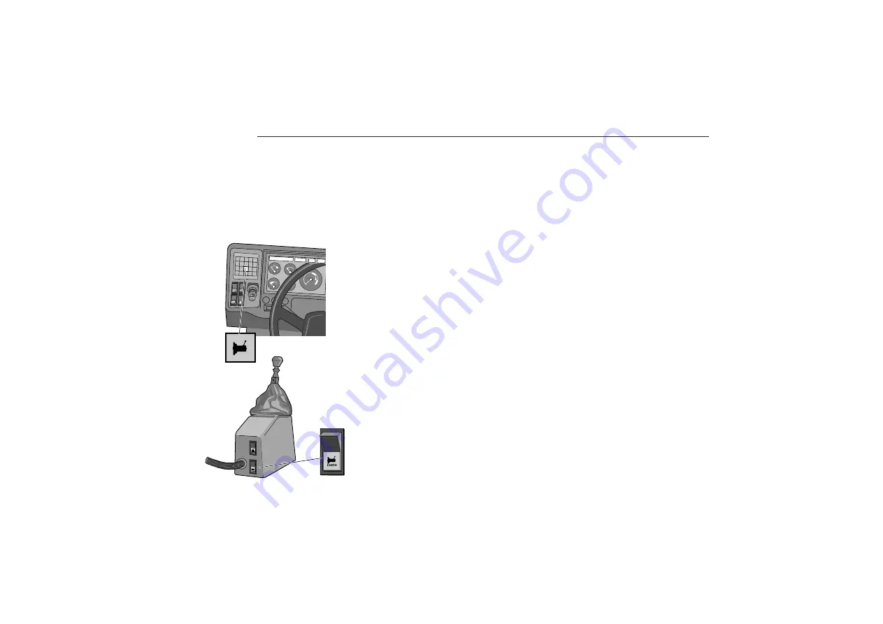
Gearbox G8 EGS

Diagnostics
switch

Diagnostics
lamp

Summary of Contents for B10M

Page 1: ...Driver s Manual...

Page 2: ...Keep this manual in the bus Read it thoroughly It contains important information for the driver...

Page 3: ...g for specific data If there is anything else you wonder over regarding service and maintenance of your B10M you are welcome to contact your dealer Due to the fact that much of the equipment in the bu...

Page 4: ...foresee risks to your passengers As the driver of the vehicle you are responsible for making sure that the safety equipment is used and is in working order Check regularly therefore the work ing order...

Page 5: ...been re moved Tighten the wheel nuts every 6 months regardless of whether the wheels have been removed or not Observe that the bus tyres and rims should be approved for the intended load and speed in...

Page 6: ...4 Pay attention to warning and indicator lights Their purpose is to warn of danger...

Page 7: ...harging 15 voltmeter 15 Instrument lighting rheostat 15 Engine Engine speed 16 Turbo pressure 16 Fuel level 16 Lubricating oil pressure level 17 Coolant temp level 18 Transmission Transmission oil tem...

Page 8: ...erature ext int 31 8 alt compressed air articulated bus 24 9 Lubricant pressure engine 17 10 Voltmeter 15 11 Oil temperature automatic gearbox 19 or 11 Turbo pressure 16 12 Gear selector automatic gea...

Page 9: ...Feed switch with start and stop buttons 14 21 Starting heater 14 22 Emergency cut out 12 23 Instrument lighting rheostat 15 24 EDC engine control system 39 82 85 25 Differential lock 32 26 Retarder s...

Page 10: ...mpartment 12 Low level coolant 18 Low level engine oil 17 Door open 33 Hatch open 33 Oil temperature automatic gearbox 19 or Diagnose EGS system 90 High temperature coolant 18 Charging generator 2 15...

Page 11: ...G8 EGS G8 MGS 44 48 Direction indicators 10 Main beam 10 Stop 33 Buzzer Sounds when one of these warning lights comes on Central warning lights Light up to indicate a warning light has come on in lam...

Page 12: ...by pull ing the lever towards the steering wheel 3 When the light switch is not on the func tion for main beam can be utilized main beam flash by pulling the lever in the same direction Cruise control...

Page 13: ...pring loaded pressure point 2 in which position the wipers operate for as long as the lever is held there When the lever is moved past the pres sure point to position 3 the wind screen wipers will ope...

Page 14: ...alarm system is working If any of these warning lights come on while driving Stop the bus and break the current using the emergency cut off switch or the battery master switch if there is no emergency...

Page 15: ...ghts off alt day running lights Parking light Main dipped beam Light switch Switches for parking lights and main dipped beam for buses with starting switch Located on the left hand side of the steerin...

Page 16: ...different positions Destination sign lighting Neutral position Check position for indicator and warning lights Drive Day running lights on Parking light on Main dipped beam on P O C 1 P Start button...

Page 17: ...arted The warning light should light up when the starter key is in the drive position and the engine is not running When the engine starts the light should go out Buses with two generators have two wa...

Page 18: ...tained When driving the engine speed should be kept in this zone as much as possible Inside the green striped engine speed zone the pulling power is also high but the fuel economy somewhat low er 3 Ne...

Page 19: ...ne starts the warning light should go out Low oil level The warning light comes on if the oil level in the engine oil tank gets too low Stop the engine and check the oil level in the level glass on th...

Page 20: ...imum permitted coolant temperature is exceeded If the light comes on while driving Stop the engine and check the temperature gauge reading If the indicator is in the red zone the coolant temperature i...

Page 21: ...p goes on If the temperature still does not drop you must stop the bus Engage neutral and raise the engine speed for a few seconds If the temperature does not drop immediately the oil level may be too...

Page 22: ...aced with a plastic disc The tachograph disc holder should never be empty Knobs 1 for the main driver and 2 for the second driver must be set according to the captions by the symbols if any thing othe...

Page 23: ...ally in place 4 After finishing work yet no later than 24 hours after the tachograph disc should be removed and the current Instruments and controls date meter reading at end of journey and distance t...

Page 24: ...backwards the handbrake is gradu ally engaged and it is fully engaged when the control is in its rear locked position Always check that the handbrake is locked in position Articulated buses that have...

Page 25: ...ight has gone out Low air pressure handbrake The warning light comes on when the handbrake is applied or if the air pressure in the handbrake circuit is too low to allow the handbrake to be released T...

Page 26: ...ssure chamber for the trailer This gauge is located in the group of instruments on the right of the steering wheel Low air pressure footbrake The warning light is connected to both brake circuits and...

Page 27: ...This means if a fault should occur on the ABS system the operation of the diagonal circuit at fault will be disconnected The normal braking function on the faulty cir cuit is however fully functional...

Page 28: ...ing the slewing brake will automatically stop the bus Emergency disengagement of slewing brake Press in this switch to continue after the slewing brake has been applied As long as the critical angle i...

Page 29: ...the open position If the bus has clamping strips their function should be regularly checked Exhaust brake The exhaust brake is a complement to the footbrake system and is activated by a foot switch T...

Page 30: ...kes are applied will activate the retarder See adjacent illustration To avoid problems on slippery roads for example the activa tion of the retarder via the brake pedal can be turned off with a switch...

Page 31: ...too low 3 The lamp will flash rapidly when the bus has not reached the desired position with respect to kneeling and levelling i e the bus is moving towards the desired end position or normal position...

Page 32: ...est position Can be used when loading unloading lug gage for example Version with raise only Pressing the bottom of the switch will raise the bus Pressing the top of the switch will return the bus to...

Page 33: ...k and tripmeter option Right button Select clock or tripmeter function Setting the clock when this is displayed See also below Hours and minutes can be set with the button The setting will change unti...

Page 34: ...oupling Differential lock option Release the catch and press the switch to engage the differ ential lock The following must be observed when engaging Engage a suitable gear depress the clutch engage t...

Page 35: ...cover equipped with indicator is open Stop Comes on when a passenger has signalled for the bus to stop Rear fog lights The indicator light is on when the rear fog lights are on NOTE The laws and regul...

Page 36: ...ur driving instructions The manner in which the bus is driven has a great bearing on the bus s reliability economy and service life The following chapter contains most of what is relevant to starting...

Page 37: ...Cruise control 58 Articulated bus 60 Steering 62 Tips for summer driving 62 Tips for winter driving 63 Daily inspection 36 Battery master switch 37 Steering wheel driver s seat 38 Safety belt 38 Star...

Page 38: ...amping strips 5 Luggage and engine hoods 6 Dashboard indicator and warning lights see page 39 7 Position of rear view mirrors 8 Safety equipment For operational reliability check the following before...

Page 39: ...d off Otherwise there is a risk that the batteries will discharge if any power sources were to be left on However there are a small number of power sources which are intended to function even when the...

Page 40: ...ng move ments which endanger passenger safety Safety belts If the bus is equipped with safety belts in the driver s seat front passenger seat centre seat etc it is the driver s re sponsibility to see...

Page 41: ...position EDC internal test If your bus is fitted with a DH10A engine with Electronic Diesel Control there will be a diagnostic lamp on the dash board see page 86 that goes on constantly when the star...

Page 42: ...e key to start position press the start button on buses with feed switch Do not touch the accelerator pedal on buses with EDC The correct amount of fuel will be supplied automatically It may be necess...

Page 43: ...pprox 600 rpm will apply until the coolant temperature exceeds approx 45 C Exhaust pressure governor The exhaust pressure governor is activated automatically when the coolant temperature is under 70 C...

Page 44: ...t lower gear should be chosen using the gear selector While driving each forward gear selection can be pre selected If gear position 2 or 1 is used at higher speeds than the cor responding driving pos...

Page 45: ...stationary When none to the above instructions are fulfilled the previ ously selected gear will be engaged and the journey can continue Kick down The accelerator pedal s wide open throttle position c...

Page 46: ...ship lever position gear position On delivery from the factory the shifting system is programmed 1 2 3 4 5 6 7 and 7 in ascending gear ratio sequence where 7 is activated with the pushbutton on the ge...

Page 47: ...ver revving Making regular use of this overrevving protection will strain the gearbox controls and synchromesh and should there fore be avoided Parking Even though the gear lever can be move to a gear...

Page 48: ...retain traction 2 3 It does not matter if you shift from 2 or 2 Press the lever slightly to the left while moving it to lever position three 3 4 Disengage third and let the lever find neutral posi ti...

Page 49: ...steep inclines where tight gear steps are needed to retain traction This gear can usu ally be skipped 2 4 3 4 Disengage the previous gear and let the lever find neutral position before moving it to le...

Page 50: ...be kept still a moment in neutral before engaging the next gear NOTE The toggle switch for the range gear should be in LOW position before starting R Press the lever to the left and then down to engag...

Page 51: ...a certain spring load must be overcome 5 6 Move the lever down past neutral with a slight press to the left to overcome the spring load Rest when passing neutral 6 7 Disengage sixth Move the gear lev...

Page 52: ...gear lever find neu tral position Move the lever straight up towards third posi tion Fourth straight down To engage fifth gear disengage fourth and press the gear lever with some force to the right a...

Page 53: ...hen driving downhill with the wheel brakes being used as supplementary braking most buses have at least one of these auxiliary braking systems Do not pump the brakes if they are needed when driving do...

Page 54: ...retarder is optional on a manual gearbox It is standard equipment in automatic transmissions integrated The retarder like the exhaust brake is a complement to the ordinary braking system Correctly use...

Page 55: ...tarder should be disengaged if the traffic con ditions allow As usual the engine s cooling capacity increases if the en gine speed is increased and this will accelerate retarder cooling The green lamp...

Page 56: ...t stages 4 and 5 have no effect in combination with automatic gearboxes Electromagnetic retarder together with manual gearbox This retarder hand control has four active positions provid ing 25 50 75 a...

Page 57: ...new increased speed when the accelerator pedal is released after overtaking or the new reduced speed when the brake pedal is released after braking Unlike normal cruise control systems that work only...

Page 58: ...dbrake can be used as an emergency brake if the footbrake system should malfunction When using as emergency brake gradually move the con trol back to parking position Hold in the lock all the time Oth...

Page 59: ...t on the accelerator and allow the gearbox to shift at low engine speeds Avoid using kick down The engine speed range that gives the best fuel economy is marked in green on the tachometer Do not chang...

Page 60: ...tch to OFF or by pressing either the brake pedal or the clutch pedal Make a practice of always using the brake or clutch peal to disengage cruise control This is so that you will react automatically i...

Page 61: ...The following description applies to buses with Electronic Diesel Control only If the engine is warm above 45 C the bus is stationary and the clutch pedal is released handbrake applied and neu tral se...

Page 62: ...aiter The trailer coach is available in two versions with steering and without steering wheels The following applies only to articulated buses with steered trailer coach as this is the most common des...

Page 63: ...very small steer ing wheel movements in the opposite direction until the de sired turning angle is obtained Then turn the steering wheel immediately in the same direction as the trailer coach Adjust...

Page 64: ...p The bus can be steered even when the power steering system is malfunctioning If the power steering suddenly ceases it may feel like the steering is locked This is not the case however but great forc...

Page 65: ...wind screen and headlamp washer reservoirs The battery should be in good condition Cold reduces the capacity of the batteries If abnormal exhaust smoke occurs after heat the en gine by pressing the co...

Page 66: ...es the fault may be easy to find and simple to rectify but it is also possible that the cause of the fault is difficult to locate This chapter is intended to increase your knowledge on the operation o...

Page 67: ...ing 73 Tyre inflation 73 Tyre choice 74 Drive belts 75 Electrical system Changing batteries 76 Rapid charging and start help 77 Changing bulbs in dashboard 77 Electrical distribution boxes 78 Fault tr...

Page 68: ...with each country s importer you will find the telephone number Third Ring Volvo Action Service any time of the day or night The telephone number can be found in the Service Guide on the page with th...

Page 69: ...m do the following Fill the handbrake circuit brake cylinder with air so that the handbrake can be released before towing When there is access to dry clean compressed air the com pressed air system ca...

Page 70: ...ect the clamp head of the enclosed tyre inflation hose to the tyre valve 3 Lower the handbrake to the drive position 4 Press the other end of the hose against the pump nipple locat ed by the pedals Pr...

Page 71: ...ewed until the brakes release Use the intended spanner from the toolkit or a 24 mm socket and ratchet spanner Count the number of rotations this will make resetting easier 3 The bus can now be towed O...

Page 72: ...the inner 1 of the two jacking points behind the front wheel marked with a symbol on the body Make sure the jack is vertically under the jacking point Then lift as far as possible with this jack 7 Th...

Page 73: ...e Make sure the jack is vertically below the jacking point and that the adapter is engaged in the hole Screw up the jack as necessary 8 Lift the bus high enough for the wheel to go free from the groun...

Page 74: ...other wheel nuts and tighten them so that the wheel is against the hub mating surface 3 Tighten the wheel nuts in the illustrated order to 200 Nm 4 Tighten a further 90 in the same order Dual mounted...

Page 75: ...se to the pump nipple on the tyre to be inflated 2 Press the other end of the tyre inflation hose to the pump nipple next to the steering shaft 3 If necessary start the engine to charge the compressor...

Page 76: ...er tyre when single mounted 150 index for highest load per tyre when dual mounted L speed index Certain tyres have a further index B which indicates that the tyre may be used with heavier loads at low...

Page 77: ...over over the engine To avoid damaging the tensioning device both fastening points must be loosened before turning the adjusting nut screw Always change both belts in a pair at the same time Volvo Bel...

Page 78: ...battery lead terminals be fore connecting them After connecting them they must be treated with anti corrosion agent Battery boxes in various designs are available from Volvo Battery installation may...

Page 79: ...or is not dimensioned for start help If start help is required use additional batteries connected in parallel to the existing bus battery Note the polarity Plus to plus and minus to minus Changing bul...

Page 80: ...00 309 3026 A 315 23 1 30 15 KB KA 23 1 354 B 345 3041 3063 3027 If anything happens 389 333 Circuit board for warning and indicator lights Fuse test Main circuit board 5A fuse for lamp check circuit...

Page 81: ...17 16A Starter circuit 18 16A Parking lights Headlights Instrument lighting 19 8A 15 to body via KB6 20 15A 15 to body via relay 3026B 21 25A to body 22 10A to body via KB3 23 8A Brake lights Relays o...

Page 82: ...e 10 on the main circuit board Relay Circuit 399A Safety relay neutral position 399B Control unit supply 3038A Polarity reverse start inhibitor 3038B Polarity reverse reverse light Fuses and relays on...

Page 83: ...ic retarder 9059 Gearbox G8 EGS Usually located behind the driver See control unit on page 92 Other fuses and relays On additional electrical distribution box Fuse Amperage Circuit 44 5A EDC controls...

Page 84: ...Fuses and relays in electrical distribution box in front end of battery box Applies to buses with original battery box located under the driver s position Fuse Amperage Circuit 34 80A Supply to elect...

Page 85: ...tact fuse may require testing If a fuse is suspected of being defective remove it from its location and press it into the socket on the far left of the row fuses on the main distribution box position...

Page 86: ...nt of the battery box see page 82 and circuit breakers 10 and 17 in the main electrical distribution box intact not triggered Check relays 315 starting switch 345 start inhibitor body 354A starting po...

Page 87: ...ution box the lamp will go on continuously Current is then fed over fuse 46 10A in the electrical distribution box in front of the core assembly The bus can be driven as normal even if the lamp comes...

Page 88: ...before the brake test is carried out The diagnostic lamp should go out after pressing and holding the brake pedal for a few sec onds If the light continues to shine then there is a fault in the con tr...

Page 89: ...E Auxiliary engine speed signal faulty 7 B Speedo readings show abnormally high speeds 8 B Vehicle speed signal faulty 9 B Charge air temperature higher then 90 C 10 B Charge air temperature abnormall...

Page 90: ...osition turn the starter key to position 0 and then back again to the drive position The follow ing information will now be provided by the diagnostic system Diagnostic lamp Fault code indicated on co...

Page 91: ...cylinder piston should not return to its rest position If it does check whether there is hy draulic fluid leaking from the servo cylinder If the piston returns without any visible leaks there may be a...

Page 92: ...l unit It can be activated with the diagnostic switch as follows Put the starter key in drive position With the gear lever in neutral and the bus stationary press the bottom of the diagnostic switch A...

Page 93: ...fault codes Once a fault has been rectified the stored fault codes are cleared in the following way Put the starter key in 0 position Press the diagnostic switch and keep pressing it while turning the...

Page 94: ...d Shifting is per formed slower than normal Separate emergency operation board If it is still impossible to change gear the emergency opera tion board can be engaged as follows Depress the catch on th...

Page 95: ...e desired height irrespective of the load Suspension height during normal operation and maximum value for raising and lowering the bus can be changed within certain limits by an authorized person afte...

Page 96: ...only once the engine has been started Actually when the alternator is charging In order to retrieve fault codes from the warning and diagnostic lamp the engine must be running or pins 1 and 2 in the...

Page 97: ...ignal Tachograph speed signal w connect leads 5 Level sensor Level sensor with levers connections and leads 6 Control period Air leaks pressure pressure sensor solenoid valves speed signal level senso...

Page 98: ...the bus in perfect working order and to maintain a high standard of passenger safety The correct choice of oil regular oil level checks and changing oil and fil ters in accordance with recommendations...

Page 99: ...dryer 123 Charging time braking system 124 Battery fluid 124 Tyres air pressure 125 Lubrication schedule 126 Maintenance and warranty 98 Engine lubricating oil 99 Hydraulic cooling fan operation 102 C...

Page 100: ...25 000 km for urban driving 35 000 km for scheduled traf fic and 45 000 km for long distance and tourism plus a major service every 12 months Instructions for oil and filter changes plus lubrication a...

Page 101: ...mber 1161976 208 litres 1161975 20 litres Using oil complying with VDS Volvo Drain Specification Urban and suburban traffic max 20 000 km Interurban traffic max 30 000 km Long distance and tourist max...

Page 102: ...tted with hydraulic cooling fan operation The fan drive oil is red It essential that all the plugs are removed or a large amount of oil be otherwise be left in the engine This has a bearing on the oil...

Page 103: ...ne oil is filled through the oil reservoir filler pipe After oil changes and other maintenance check the level of the oil in the oil reservoir level glass It should be between the MAX and MIN markings...

Page 104: ...rther 1 2 to 3 4 of a revo lution 4 Fill with oil to the top of the level glass 5 Start the engine Check the tightness around the filter 6 Stop the engine check the oil level and top up to the top of...

Page 105: ...protect against frost It provided good protection against corrosion Draining coolant All drain points must be open to completely drain the sys tem The expansion tank cap should also be removed when d...

Page 106: ...ing systems where the level of coolant is above the level in the expan sion tank the coolant must be pumped up by starting the system s circulation pump Gradually top up through the expansion tank unt...

Page 107: ...lant change and then every 6 months Close the valve on the filter housing before removing the fil ter so that the coolant does not run out Open pin vertical closed pin horizontal Use a filter wrench t...

Page 108: ...someone un authorized all warranties will become void Fuel filter The degree of purity of the fuel is of great importance for the lifetime of the filter Symptoms of a blocked filter are deterio rated...

Page 109: ...mpty filters with fuel Condensation Once a year suitably in the autumn the fuel tank bottom plug should be removed to allow for possible sludge and condensation to run out By doing this the risk of wa...

Page 110: ...ction pipe has followed up with the oil filter from the gearbox casing it must be refitted with a new O ring C Make also sure that the upper O ring B on the oil filter is in place and intact Tightenin...

Page 111: ...The oil level should remain in the area marked cold on the dipstick Top up if the oil level is too low NOTE In extremely cold weather conditions the oil level di rectly after starting may be below th...

Page 112: ...s with new copper gaskets and tight en to 50 Nm 4 Drain any oil in the filter housing through the drain hole at the bottom of the filter housing 5 Remove the filter housing cap 6 Change the filter ins...

Page 113: ...erature in other words at least 60 C Gearbox oil nor mally has approximately the same temperature as the bus coolant Stop on a level surface engage the handbrake and let the engine idle with the gear...

Page 114: ...o the correct level Start the engine and run it for about one minute Check the tightness around the filter Check the oil level and adjust if necessary Make sure the O ring sealing between the filter c...

Page 115: ...be used Recommended at low temperatures see viscosity scale note 3 Volvo Synthetic oil part no 1161904 for 20 litre pack 1161906 for 208 litre pack Temperatures refer to constant ambient temperatures...

Page 116: ...w the plug in the level filler hole The oil level should reach the bottom of the hole Drain Level filler Change gearbox oil every 90 000 km but at least once a year Halve the interval for changing whe...

Page 117: ...e used Recommended at low temperatures see viscosity scale Volvo Synthetic oil part no 1161904 for 20 litre pack 1161906 for 208 litre pack Temperatures refer to constant ambient temperatures 1 When d...

Page 118: ...arder housing The level should reach between the min and max marks on the dipstick or to the bottom of the level hole Top up if needed The difference in volume be tween min and max is approximately 1...

Page 119: ...hat the plug 6 in the bottom of the heat exchanger is for draining coolant 4 Fit a new sealing washer to each plug Tighten the large plug to 150 Nm and the small one to 66 Nm 5 Measure up exactly 6 li...

Page 120: ...must not be used Check clutch fluid level Check the level at every basic service The level should be in the middle of the reservoir Change fluid every three years annually when driving at altitudes ab...

Page 121: ...his is essential to avoid leaks caused by over pressure in the rear axle Oil change volume Approx 20 l Oil change interval for rear axle RAEV 80 85 Oil change when using Volvo 97312 transmission fluid...

Page 122: ...r 20 l package Check oil level Check the level in the oil reservoir with the dipstick The check should be performed with the engine at a stand still The level should be at MAX If it is lower top up wi...

Page 123: ...ed at the same time for those buses that have double inserts One with a smaller inner diameter inside the other The air cleaner filter cannot be cleaned It they should be changed Periodic inspections...

Page 124: ...s to establish if there is damp or oil in the compressed air Oil found in the air is a sign of damage to the compressor Oil found in the air from the compressor also destroys the drying agent in the a...

Page 125: ...d away Dehumidi fication of the compressed air occurs through the ceramic a filter It they should be changed every other year or when oil or water is found after draining the compressed air tanks See...

Page 126: ...till 400 kPa 2 4 kp cm2 should be reached in 1 to 2 minutes The charge capacity indicates the condition and working order of the compres sor Battery fluid The fluid level should be 10mm above the batt...

Page 127: ...cording to these certain kinds of driving can warrant an increase in tyre pressure of 0 5 1 0 kp cm2 50 100 kPa Dual mounted wheels With dual mounted wheels use only tyres of the same type and roughly...

Page 128: ...tive and consist ence to NLGI no 2 Volvo part no 1161315 High temperature grease Volvo part no 1161251 Body Doors and hatches covers nipples to be lubricated with grease otherwise a few drops of oil o...

Page 129: ...t spider Propeller shaft front spider rear spider Brake cam Brake cam Brake cam Spindle bolt bearing top cover x 2 bottom cover Steering axle upper sliding joint does not normally require lubrication...

Page 130: ...128 Remember When contacting your Volvo garage or when ordering spare parts the type designation and serial number of the chassis and the components must be specified...

Page 131: ...129 TechnicalData Type plates 130 Specifications Data 132...

Page 132: ...s Sweden 56789 VIN YV3R2FH18A NA000008 Engine type designation component number and serial number Punched on top of engine block by injector pump Gearbox type designation and serial number ZF manual g...

Page 133: ...If national gross vehicle weight or axle weight regulations are prescribed to lower levels then the recommended the general agent importer should stipulate this on the left side of the type plate wit...

Page 134: ...10A which fulfil special legal customer or adaptation requirements THD102KF Output kW hp 180 245 at rps rpm 37 2200 Torque Nm kgf m 1050 107 at rps rpm 21 1250 THD102KB Output kW hp 210 286 at rps rpm...

Page 135: ...o gearbox through an electropneu matic shifting system For a description of the difference between the two G8 EGS gearbox variants 2 and 7 see the chapter Driving VOLVO G8 MGS Mechanical Gear Shift Me...

Page 136: ...84 1 VOITH D863 3 D864 3 Fully automatic gearbox Shifting points are controlled by an electronic unit Torque converter functions also as a re tarder D863 3 D864 3 Gear Gear ratio hydraulic step engine...

Page 137: ...864 3 159 148 139 124 108 97 5HP500 140 130 122 109 95 85 590 600 G8 E MGS 116 108 101 90 79 71 S6 85 4HP500 590 The control system for the DH10 engine makes it possible to limit the top speed to a de...

Page 138: ...front axle 3055 cm2 rear axle 3810 cm2 trailing wheel axle bogie 2675 cm2 trailer coach axle steered 3055 cm2 trailer coach axle rigid 3810 cm2 Braking system operating pressure 7 5 0 1 kp cm2 Compres...

Page 139: ...he coach builder Weights Two axle version Max front axle weight 7500 kg Max drive axle weight 10500 12000 kg Max gross vehicle weight 18000 19000 kg Three axle version Bogie version Max front axle wei...

Page 140: ...change 103 filter 105 level 18 104 temp level 18 Cruise control 10 58 Daily inspection 36 Dashboard 6 Data 129 Differential lock 32 Direction indicators 10 Door brake 27 Draining compressed air syste...

Page 141: ...riodic inspection 121 Power steering 62 Preventive maintenance 98 Puncture 70 Rapid charging 77 Releasing handbrake 68 Retarder 28 52 oil change hydraulic 116 Reverse gear data 135 oil level change 11...

Page 142: ...140 Notes...

Page 143: ...141 Notes...

Page 144: ...142 Notes...

Page 145: ...143 Notes...

Page 146: ...144 Notes...

Page 147: ...3 Notes...

Page 148: ...Volvo Bus Corporation TP 9273 1 English...

Reviews: