


52
USA-Execution
Cable marking
Design.
AWG
Colour
mm
2
A
9
Ivory
6
B
15
Black
1.5
B'
19
Black
0.6
C
9
Red
6
C'
13
Red
2.5
C''
1
Red
35
D
13
Green
2.5
D'
15
Green
1.5
D''
19
Green
0.6
E
15
Grey
1.5
F
15
Yellow
1.5
G
15
Brown
1.5
H
15
Blue
1.5
H'
11
Blue
4
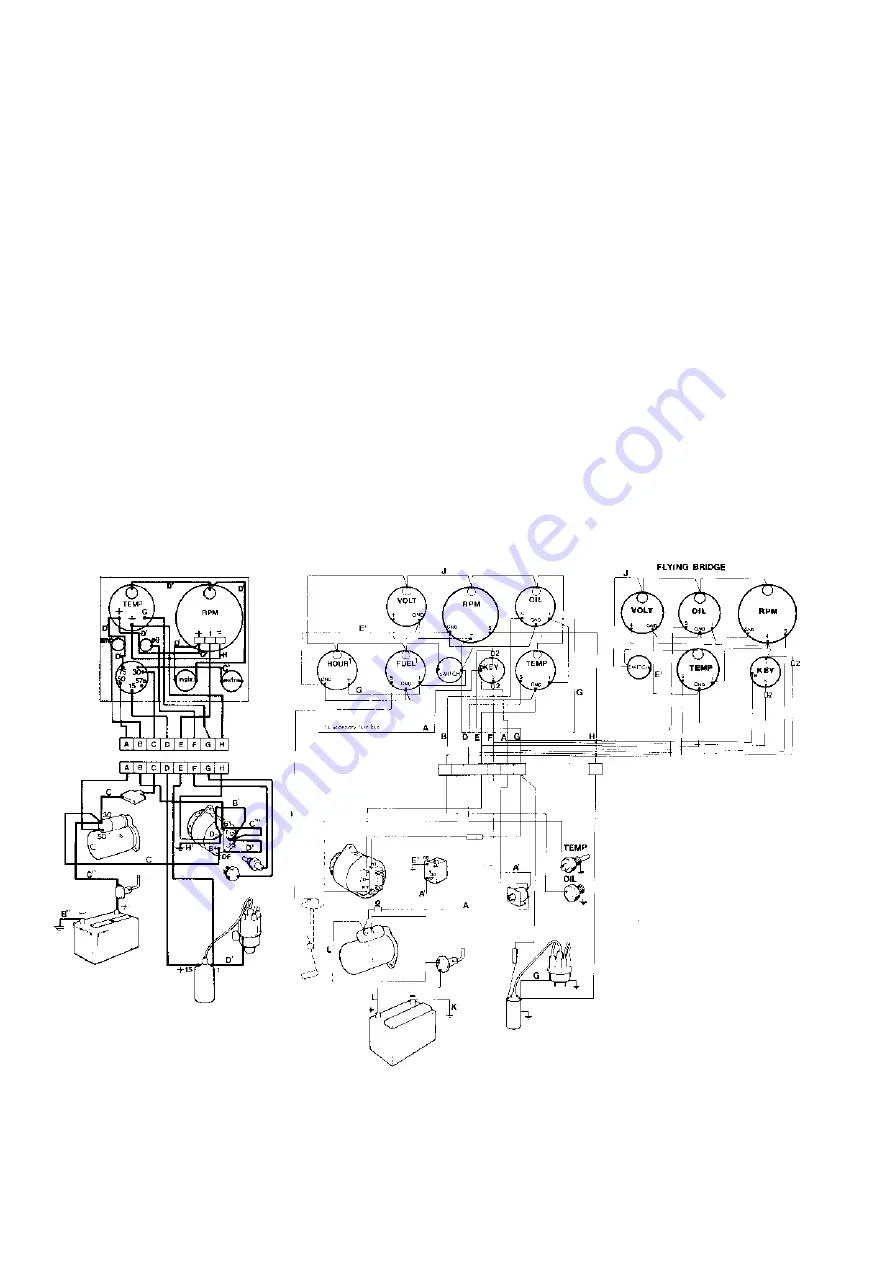
ELECTRIC WIRING DIAGRAM
INSTRUMENT PANEL ENGINE
Position list
1.
Key switch with start
button
2.
Switch for instrument
lighting
3.
Temperature gauge
4.
Oil pressure warning lamp
5.
Tachometer
6.
Charging warning light
7.
Switch (extra)
8.
Junction box
9.
Battery
10.
Main switch
11.
Starter motor
12.
Charging regulator
13.
Alternator
14.
Fuse
15.
Oil pressure sender
16.
Temperature sender
17.
Ignition coil
18.
Distributor
Cable marking
USA-Execution see page 53
Summary of Contents for AQ125A
Page 1: ...Workshop Manual Engine Unit AQ125A B AQ145A B C 2 0 ...
Page 2: ......
Page 74: ...7739856 8 English 11 1998 ...


