Axpert MEX-1500/ MEX-3000 Service manual
21
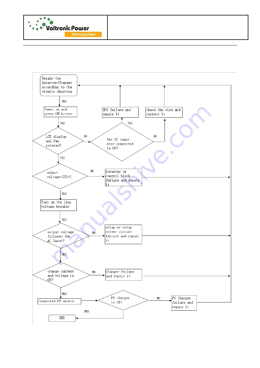
7. Test Step
Page 1: ...Axpert MEX 1500 MEX 3000 Service manual 1 Axpert Charger Inverter Service manual...
Page 2: ...Axpert MEX 1500 MEX 3000 Service manual 2 Revision Description Prepared by Approved by V00 Initial draft release Rondo 2016 3 25...
Page 3: ...3 4 Charger 10 4 Functional explanations for each PCB 11 4 1 Main board 11 4 2 CNTL board 11 4 3 SCC board 11 4 4 COMM board 12 4 5 LED board 12 5 Interface 13 5 1 LED Indicator 13 5 2 LCD Display Ic...
Page 4: ...Electric Specifications this section show you the basic electric specification of the Inverter Charger 1 2 Important safety instructions WARNING This chapter contains important safety and operating i...
Page 5: ...re provided as over current protection for the battery supply 11 GROUNDING INSTRUCTIONS This inverter charger should be connected to a permanent grounded wiring system Be sure to comply with local req...
Page 6: ...ng functional blocks as shown in figure 2 1 PWM SCC EX MPPT SCC MEX DC AC Inverter AC DC Rectifier DC DC Converter Charger DC Fuse Input Breaker Thermal Switch Protection to NTC Sensor to NTC Sensor R...
Page 7: ...primary and secondary these dots show starts of the winds When Q36 is ON the dot ends of all winds are positive with respect to their no dot ends Output rectifier diodes D70 D67 D54 and D57 are rever...
Page 8: ...40 Q26 Q25 Q39 and Q38 Q21 Q22 Q63 Q13 Q18 Q23 Q35 receive 180 out of phases Refer to figure 3 2 the battery voltage is transformed through a full bridge DC DC converter to 330Vdc as DC BUS for invert...
Page 9: ...drive high energy and high speed power of MOSFET and IGBT with independent high and low referenced output channels To construct a high frequency PWM inverter the drivers receive switching signals from...
Page 10: ...he batteries with a constant current at initial stage and as battery voltage keep increasing the charge current decrease accordingly until the charge voltage reached the constant voltage level and the...
Page 11: ...G 1 13 SCC 71 500565 XXG 1 14 COMM 71 500567 XXG 1 15 LED 71 500238 XXG 1 Note XX in the serial number is the version of the PCB 4 1 Main board The main board consists of SPS DC DC converter inverter...
Page 12: ...uipped with a communication port to communicate with a PC with corresponding software Please use supplied communication cable to connect to communication port of this inverter and USB port of the PC 4...
Page 13: ...r LED Indicator Messages Green Solid On Output is powered by utility in Line mode Flashing Output is powered by battery or PV in battery mode Green Solid On Battery is fully charged Flashing Battery i...
Page 14: ...oltage and charger current Configuration Program and Fault Information Indicates the setting programs Indicates the warning and fault codes Warning flashing with warning code Fault lighting with fault...
Page 15: ...nd the other two bars will flash in turns 2 167 V cell Bottom three bars will be on and the top bar will flash Floating mode Batteries are fully charged 4 bars will be on Battery level icon will prese...
Page 16: ...onnects to the PV panel Indicates load is supplied by utility power Indicates the utility charger circuit is working Indicate the solar charger circuit is working Indicates the DC AC inverter circuit...
Page 17: ...ecking c Replace the failure components d Static checking e Power up checking f Test after repair Following section will help service person to solve most of problem 6 1 Fault Reference Code Fault Cod...
Page 18: ...1 Re charge battery 2 Replace battery No response after power on No indication 1 The battery voltage is far too low 1 4V Cell 2 Battery polarity is connected reversed 1 Check if batteries and the wir...
Page 19: ...the air flow of the unit is blocked or whether the ambient temperature is too high Fault code 02 Internal Inverter component over 100 C Fault code 03 Battery is over charged Return to repair center Th...
Page 20: ...A1 QB2 QC1 QD2 Resistance 206K CE short or open 237K GC short or open 46K GE short or open Resistance R48 R144 R137 R140 Resistance 47 ohm short or open Photo coupler U1 U2 U3 U4 Resistance pin2 pin 3...
Page 21: ...Axpert MEX 1500 MEX 3000 Service manual 21 7 Test Step...
Page 22: ...ac 7V Appliances High Loss Voltage 280Vac 7V High Loss Return Voltage 270Vac 7V Max AC Input Voltage 300Vac Nominal Input Frequency 50Hz 60Hz Auto detection 55Hz as boundary Low Loss Frequency 40 1Hz...
Page 23: ...rated power for 5sec Nominal DC Voltage 12Vdc 24Vdc Cold Start Voltage 11 5Vdc 23 0Vdc Low DC Warning Voltage load 20 11 0Vdc 10 7Vdc 22 0Vdc 21 4Vdc load 20 Low DC Warning Recovery Voltage load 20 1...
Page 24: ...g current 30Amp 60Amp 90Vac 170Vac Solar Charging Mode MPPT Axpert Model MEX 1500 12 MEX 1500 24 MEX 3000 24 Charging Current 40Amp Max PV Array Open Circuit Voltage 100Vdc PV Array MPPT Voltage Range...