background image

Digital Video Recorder 

VODVR 3416

VODVR 3416

VODVR 3416

VODVR 3416    


47

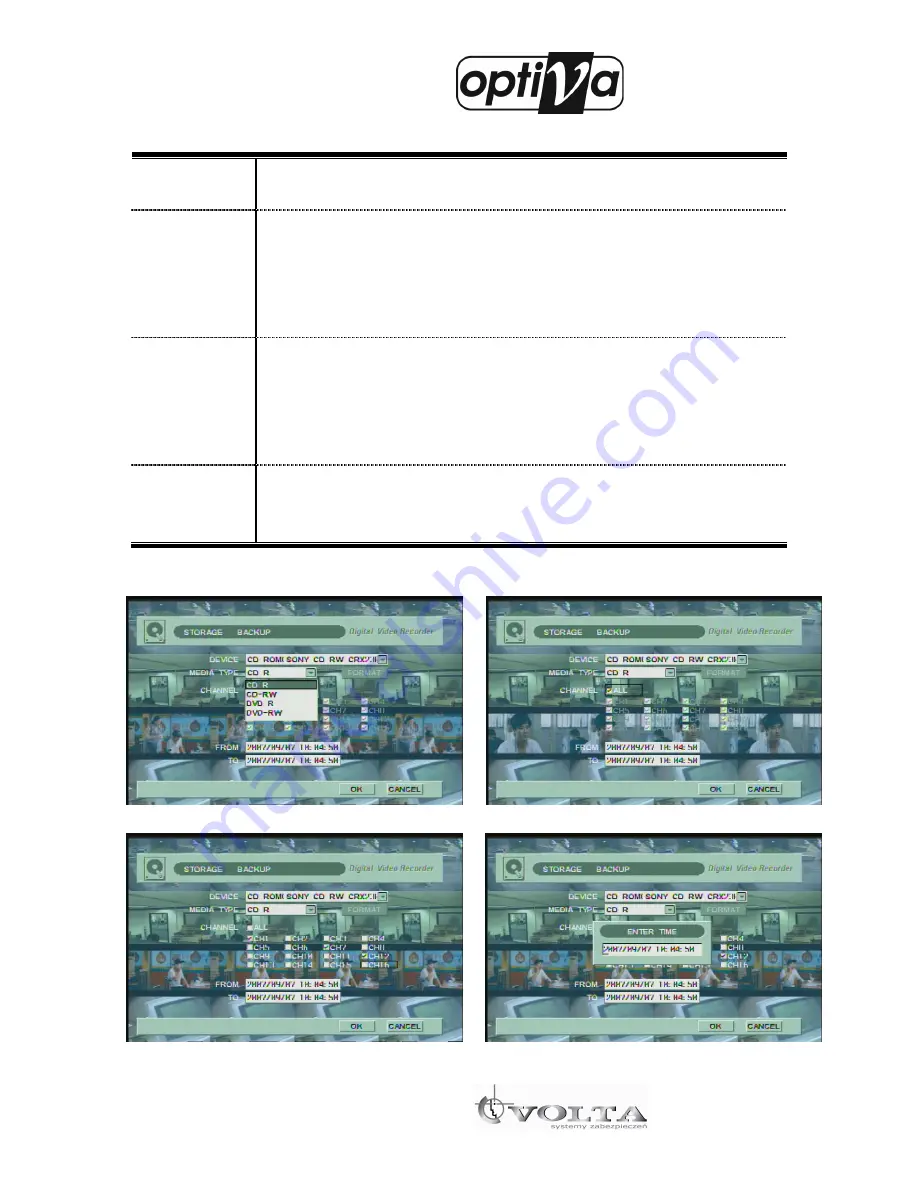
It is the explanation of the BACKUP set-up. 

    After that process, click OK button then backup process is start. 

    You have to wait for image processing on system before save on media in case of backup to ODD. 

                                                                        Figure 4-47                                                                              Figure 4-48 

DEVICE 

This  section  display  specification  and  information  of  USB  memory  stick,  CD-RW  or  DVD-

RW for backup as figure 4-46. 

MEDIA TYPE 

You  can  select  CD-R,  CD-RW,  DVD-R,  DVD-RW,  and  USB  MEMORY  for  the  BACKUP 

MEDIA.  And  you  can  select  format  of  media  by  format  button  to  minimize  any  kinds  of 

backup problems. It support CD-R/ CD-RW/ DVD-R/ DVD-RW as Figure 4-47. This media 

type is for backup media not player device.   

*CAUTION: DVR supports only DVD-R media, not DVD+R media. 

CHANNEL 

It  assigns  the  BACKUP  target  channel.  All channels  are  assigned  when  ALL  is  selected,  if 

you want choose specific channel, click ALL button for disable all channels. After that click 

specific channel which you want to backup.   

It’s assigned backup targets are all channel on media type as Figure 4-48. 

If you want to choose all channels, click the check box ALL. 

TIME 

It’s  assigned  start  to  end  time  of  backup  data,  click  the  specific  table  of  time  “FROM”  and 

click SEL button as Figure 4-50, then you can see time selection box. Push numeric button 

on the front panel or remote controller to input specific time. 

Summary of Contents for Optiva VODVR 3416

Page 1: ...Digital Video Recorder VODVR 3416 VODVR 3416 VODVR 3416 VODVR 3416 User Manual...

Page 2: ...rder VODVR 3416 VODVR 3416 VODVR 3416 VODVR 3416 2 THE LIST OF CONTENTS This Product is the triplex MPEG 4 DVR DVR SET CLIENT SOFTWARE CD REMOTE CONTROLLER BATTERY MANUAL SCREWS SATA HDD CABLE HDD BRA...

Page 3: ...put Support during Recording 5 S VHS It displays the image of S VHS 6 AUDIO IN It is the audio input jack for the real time audio input 4 CH supports 7 NETWORK It supports the TCP IP network through R...

Page 4: ...Digital Video Recorder VODVR 3416 VODVR 3416 VODVR 3416 VODVR 3416 4 Control...

Page 5: ...the LOG to operate the DVR function 14 REW It replays the search image backward up to 128 times faster and supports the STEP Rewind function at the pause 15 PLAY PAUSE It plays pauses the image during...

Page 6: ...DING TO INSTRUCTIONS See INSTALLION INSTRUCTION BEFORE CONNECTING TO THE SUPPLY THIS EQUIPMENT AND ALL COMMUNICATION WIRINGS ARE INTENDED FOR INDOOR USE TO REDUCE THE RISK OF FIRE ELECTRIC SHOCK DO NO...

Page 7: ...les The manufacturer is not responsible for any damages caused by improper use of the product or failure to follow instructions for the product The manufacturer is not responsible for any problems cau...

Page 8: ...er 4 Setting up the DVR System 18 1 SETUP LIVE 18 1 1 DISPLAY 19 1 2 COLOR 20 1 3 SEQ DWELL TIME SINGLE 20 1 4 SEQ DWELL TIME QUAD 21 1 5 SPOT DWELL TIME SINGLE 21 1 6 SPOT DWELL TIME QUAD 22 1 7 POSI...

Page 9: ...RCH SEARCH BY CALENDAR 61 3 SEARCH SEARCH BY EVENT 62 4 SEARCH GO TO FIRST AND GO TO LAST 63 Chapter 6 FUNCTION 64 1 PTZ 64 1 1 PTZ GENERAL PTZ 64 1 2 PTZ ADVENCE PTZ 65 2 SPOT 67 3 SEQUENCE 67 4 AUDI...

Page 10: ...US CONTROL 81 2 7 LOCK SCREEN 82 2 8 SNAP SHOT 82 3 SEARCH FEATURE 83 3 1 Main Search Screen 83 3 2 Search Button Feature 84 3 3 Remote Search Selecting the recorded date and time 86 3 4 Local Search...

Page 11: ...T changes to GREEN and the SYSTEM BOOTING is started when the POWER BUTTON of the FRONT PANEL and Remote Controller is pushed HDD The LED LIGHT is blinking when the video or audio data is stored in th...

Page 12: ...ion It rotates the image between FULL MODE and QUAD MODES The image is displayed on the monitor through the SPOT PORT PIP Picture In Picture It displays a small pop up screen on the full screen With t...

Page 13: ...Digital Video Recorder VODVR 3416 VODVR 3416 VODVR 3416 VODVR 3416 13 1 3 System Specifications...

Page 14: ...ff system If press the OK icon The DVR System will turn off immediately The POWER LIGHT of the front panel s turn on RED when the AC power is supplied and changes to GREEN when the SYSTEM starts to op...

Page 15: ...een after the system booting Figure 2 1 and the booting process is started to operate Figure 2 2 The authentication process is started for the security of the system Figure 2 2 when the booting proces...

Page 16: ...status of the system is alarm detection The connection of the device that is connected to USB The current status of the system is PTZ control status The current status of system is backup status The c...

Page 17: ...e menu push the menu push the SEL SEL SEL SEL button and button and button and button and menu menu menu menu button is back to the main button is back to the main button is back to the main button is...

Page 18: ...NESS CONTRAST and COLOR of CAMERA SEQ DWELL TIME SINGLE It sets up the time interval between the images of each CAMERA which are displayed progressively in full screen SEQ DWELL TIME QUAD It sets up t...

Page 19: ...or not the camera number of each channel in live screen CAMERA BOADER ON OFF It selects show or not the outline of channel LANGUAGE Select It selects the language to use If you select a language the l...

Page 20: ...window sets up the channel is displayed at the right side of the screen It moves the cursor to set up Therefore please press the left and right button After finish you must press the OK button If you...

Page 21: ...he time interval between the images that are rotated in each QUAD MODE set up from 0 to 9 normally The set value for each time is 0 99 seconds and set inner 10 seconds If it operates the sequence func...

Page 22: ...ssively displayed in QUAD screen Figure 4 7 It is sets up the time interval to display the image progressively in monitor For its setup place the cursor on the time setup category of each quad channel...

Page 23: ...the video position of the each channel though to the left right button It is from 0 to 10 that to control the value According to the capacity of monitor the video position is should seen to non stand...

Page 24: ...een at the motion or sensor detection 1 8 3 VGA RESOLUTION It can select appropriate VGA resolution according user s VGA Monitor VGA resolution 800 600 1024 768 1280 1024 1 8 4 VIDEO DETECT It sets up...

Page 25: ...eview name position SHOW ON OFF It selects display camera video or not AUDIO CH1 CH4 For 120Frame The value to select is from CH1 to CH4 16 and NONE The each audio channel can move from ch1 to ch16 in...

Page 26: ...eric icon Please press the numeric icon then it makes fill the selected numeric CAP It is the icon which is selected a capital letter or a small letter of English If press the cap key on the capital l...

Page 27: ...annel 2 1 4 Channel section It assigned channel section It s two division of 1 8ch and 9 16ch for 16ch model and only one of 1 9ch for 9ch model 2 2 PTZ PROTOCOL It selects various protocols such as P...

Page 28: ...Right buttons and zoom in out buttons for arrange preset position as Figure 4 16 After finish icon image changed to icon as Figure 4 15 If you want to disable arranged preset section click icon image...

Page 29: ...e screen of the scan point Each preset range has time difference as assigned interval time It assigned PTZ preset number as you set 2 3 1 PTZ PRESET of preset number as Figure 4 17 Move cursor to pres...

Page 30: ...Digital Video Recorder VODVR 3416 VODVR 3416 VODVR 3416 VODVR 3416 30 Figure 4 18 3 RECORD It is for the record setup of the DVR system Figure 4 19 Figure 4 19 is for the record Menu...

Page 31: ...C PROPERTY It sets up the image store resolution of the entire channel in 360x240 720x240 and 720x480 It selects the Store Frame Rate for each channel in 1 2 4 8 15 30 It selects the recording quality...

Page 32: ...cord quality Frame rate for Event situation Motion Sensor Manual recording IMAGE QUALITY can be reduced from BEST HIGH NORMAL BASIC NORMAL Use this menu to specify the record quality Frame rate for No...

Page 33: ...ss the ok button It s not set up 3 3 MOTION DETECTION It sets up the field on the image motion such as motion sensitivity and motion field And It sets up the alarm out channel each video input channel...

Page 34: ...the motion area please press SEL button then it sets up the ALL and PART If it sets up to OFF label of the motion area the motion recording is not operates in DVR system Figure 4 23 The entire image...

Page 35: ...ty as high as the number is better than 0 label 3 3 3 ALARM OUT It sets up the channel of alarm device There is the single unit channel and multi unit channel Place the cursor on the field number of a...

Page 36: ...sensor channel 16ch has 16 sensor channel As Figure 4 29 it consists of Recording channel Sensor type Alarm out port by sensor channel for systematic operation 3 4 1 THE ASSIGNED RECORDING CHANNEL It...

Page 37: ...channel Figure 4 30 3 4 2 SENSOR TYPE This sensor device has two types of NC NORMAL CLOSE and NO NORMAL OPEN Users should select NC or NO type on DVR system to operate the exterior input sensor for sp...

Page 38: ...time of the motion or sensor detection Figure 4 32 It will be save recording data from the motion or sensor detection to the selected range of pre recording time POST REC TIME For the recording mode...

Page 39: ...16 VODVR 3416 VODVR 3416 VODVR 3416 39 Figure 4 32 3 6 OPTION The menu is the other functions of recoding which consist of CONTINUE REC for continuous record ON OFF and Water Mark for prohibit tinsele...

Page 40: ...ording type It continuously stores the image when it is ON mode The set point for the recording is stored as the REC PROPERTY of Chapter 4 3 1 if it is off mode It records the image by the EVENT recor...

Page 41: ...et points with the number buttons on the remote controller after placing a cursor on each field The set up of network is completed by pushing MENU button when the input of set points is finished Figur...

Page 42: ...ork by typing in the ID and password that are authenticated to users by ISP Figure 4 38 shows the progress of authentication registration for PPPOE Place the cursor on the blank and push the SEL butto...

Page 43: ...their own separate management There are four DDNS server as Figure 4 40 Among them which four DDNS server OFF means disable the others are enable IPUPDATER COM and DYNDNS ORG are world wide and free...

Page 44: ...a lot Figure 4 42 shows the network port of the default set up Ltd This port is good to use Each port is required for RMS operation and should be assigned 4 3 3 WEB PORT It is used with WEB MONITORING...

Page 45: ...ve connection on RMS and it intercepts the connection of unregistered ID ID and password that are registered on the system should be typed in to connect the RMS For the registration place the cursor o...

Page 46: ...t type as below the list Figure 4 45 As figure 4 45 Only HDD can format process But ODD CD RW or DVD RW drive cannot format ODD device don t display in Format menu 5 2 BACKUP It stores the saved image...

Page 47: ...ackup problems It support CD R CD RW DVD R DVD RW as Figure 4 47 This media type is for backup media not player device CAUTION DVR supports only DVD R media not DVD R media CHANNEL It assigns the BACK...

Page 48: ...n extend Max 4 HDD additionally If Type select extend when the internal disks are full DVR system copies a data file which will be erased because of overwriting to USB HDD If It select SHOW It shows t...

Page 49: ...you have the admin authority you can control the setup for DVR system The Admin has a full authority to control the DVR system If you have the user authority OVERWRITE Overwrite existing data when ha...

Page 50: ...rent time date format time format world wide time zone Day Light Saving DLS s start end time and Time sync as Figure 4 54 6 2 1 CURRENT TIME It displays the current time of DVR system for checking DVR...

Page 51: ...56 Push SEL key on the menu and then you can select 24 or AM PM If you choose 24 HOUR the time display is 15 00 at PM 3 o clock and if you choose AM PM the time display is PM 3 Figure 4 56 6 2 4 TIME...

Page 52: ...Start and End time as Figure 4 58 and DLS applies within the specific time as you assigned To assign Start or End time put time by using numbers on the Front Panel Key Pad or on Remote Controller If y...

Page 53: ...2 1 If you need to change time on the DVR select CHANGE TIME icon and then select SEL key It shows ENTER TIME on the window box And then input date time by using numeric key on Front Panel key pad or...

Page 54: ...t during network update due to increased network traffic Figure 4 62 This is to choose update method as Figure 4 62 You click UPDATE icon and then choose one of them by using scroll key And click OK i...

Page 55: ...com is for network update server URL as a factory default But file name could be changed without notice So check it with your vendor Network update takes more time than USB update does and processing...

Page 56: ...ich DVR system automatically calls This configuration file should be saved on USB root path and it s recommended to save on your PC not on USB for safety Figure 4 66 This is to load configuration file...

Page 57: ...to 02 as the SYSTEM ID says on the setup menu To use SYSTEM ID 02 you have to press Remote Controller ID button and 0 and 2 on Remote Controller s too 6 5 2 KEY TONE It assigns key sound when you pus...

Page 58: ...ssing mouse on off button keyboard changes to DVR control mode or PTZ camera control mode 5 When keyboard indicates DVR mode press DVR system ID by using number button of keyboard and press ENT button...

Page 59: ...ber button 3 F1 F1 F1 F1 Full screen mode 4 F2 F2 F2 F2 4ch screen mode 5 F3 F3 F3 F3 9ch screen mode 6 F4 F4 F4 F4 16ch screen mode 7 MENU AUTO MENU AUTO MENU AUTO MENU AUTO Sequence mode 8 AUX AUX A...

Page 60: ...you change channel Press number button and press ENT button Ex If you want to go to channel 7 press press Chapter 5 SEARCH Figure 5 1 This menu searches the saved image data by time date calendar or e...

Page 61: ...lace the cursor on the data that you want to search with the scroll keys and push the SEL button Figure 5 3 The existence of the image data is indicated and the image data is searched when the date to...

Page 62: ...he event of motion sensor and video loss If you select the event for motion you can see the recording data for motion per date time and video channel REW It rewinds the image data to replay the passed...

Page 63: ...el3 channel7 The thirdly you select the motion and Please press the SEARCH icon Figure 5 6 Figure 5 7 Figure 5 6 and Figure 5 7 are the shown recording data by event search and are done with the file...

Page 64: ...DIO BACKUP and LOG VIEW for DVR system These functions also have simple key of the Remote controller and Front panel key pad If you want to operate the functions move cursor to work in menu Figure 6 1...

Page 65: ...his PTZ control bar for PTZ preset and PTZ SCANPOINT as chapter 4 2 3 PTZ Preset to 2 4 PTZ scan point includes Focus control and Auto Focusing If camera supports 1 2 1 FOCUS Click AUTO icon for auto...

Page 66: ...ed by or as Figure 6 3 PTZ ADVANCE control bar 1 2 4 SCAN Figure 6 4 Click SCAN icon as Figure 6 3 PTZ ADVANCE on the Control bar and the display scrolls as assigned SCANPOINT number of chapter 4 2 4...

Page 67: ...ure 6 5 2 SPOT Figure 6 6 It supports single Spot and quad Spot through SPOT output connector Please refer to the content of Chapter 4 Live Spot Page 18 3 SEQUENCE Figure 6 7 Figure 6 8 Click sequence...

Page 68: ...n select the audio output to turn on of off by choosing AUDIO ON or OFF Figure 6 9 and the audio output can be stopped by MUTE Figure 6 9 Audio Connection of DVR System Audio Input Audio Input Audio I...

Page 69: ...Backup Figure 6 10 6 LOG VIEW This function confirms the overall operation LOG in the DVR system Push the FUNCTION KEY and select the LOG VIEW at the screen of Figure 6 1 You can choose LOG type If yo...

Page 70: ...0 Figure 6 11 Chapter 7 OTHER FUNCTION 1 DIGITAL ZOOM This function is ZOOM for DVR system not PTZ camera on LIVE view and Playback Figure 7 1 Digital zoom has 2x and 4x push ZF button on the front pa...

Page 71: ...FULL SCREEN With the PIP BUTTON the previous image is shown as CH No 1 in the FULL SCREEN and the another image is played as CH No 2 in the small pop up screen The sizes of the two screens are interc...

Page 72: ...vate IP on network you have to set private IP on DVR system STEP 3 Normally IP router uses 192 168 0 1 or 192 168 1 1 on the network so we recommend 192 168 0 5 later or 192 168 1 5 later Example WAN...

Page 73: ...Change screen mode If you press right button of mouse on screen following window will appear If you double click specific channel screen changes full screen mode If you want to go back to previous mod...

Page 74: ...ove to previous mode For enter number at password window or setup menu click mouse to active number button Then number button will appear Go to Setup menu Start or Stop recording Go to Seach menu Go t...

Page 75: ...order VODVR 3416 VODVR 3416 VODVR 3416 VODVR 3416 75 EnNet Client Software Release Version 2 5 EnNet client is the software for controlling the system through the network Any copy or change would be p...

Page 76: ...tall 3 Client Program install icon will appear install the file or name the folder differently and install 4 Once Installation is complete Network Client Program EnNet Icon will appear on the desktop...

Page 77: ...6 VODVR 3416 77 2 MONITORING FEATURE 2 1 Starting Program Double click Client Program icon on the window desktop to start the program Below image will appear for few second before Client Program appea...

Page 78: ...search data SETUP Use the button to go to setup mode E MAP Indicate where camera is installed LOCK Locking the screen of running function LOCAL MANUAL RECORD Save DVR s data in Client PC PTZ CONTROL C...

Page 79: ...ame Type in site name of DVR IP Address Type IP address of Remote DVR If using DDNS Type DDNS ID in this field DDNS ID If you use DDNS Type your DDNS ID If you select Content of DDNS IP Address change...

Page 80: ...ber of Remote DVR s channel connected Figure 3 Monitoring Screen Once Client Program is connected to Remote DVR event information will display on the list and you can search information at your reques...

Page 81: ...hosen live feed screen will store in chosen folder of Client Program menu 2 To stop storing click Record button You can click Search button and local search to play stored file 2 6 PAN TILT ZOOM FOCUS...

Page 82: ...ntrol function 2 7 LOCK SCREEN 1 Click lock button then chosen lock screen from the Client Program menu function will run 2 Type saved password 2 8 SNAP SHOT 1 Click SNAPSHOT button then live feed scr...

Page 83: ...ton then you can capture stored image or can go to Search Screen without Printing 3 SEARCH FEATURE 3 1 Main Search Screen Click Search icon in the main screen of client program then main Search screen...

Page 84: ...e arrow to choose wanted date 4 6 9 13 16 Screen Divisions mode Next Screen Full Screen and Panorama Search BACKUP Backup button LOCK Lock the screen SNAP SHOT SNAPSHOT button EVENT Event button LOCAL...

Page 85: ...6 VODVR 3416 85 Play the stored data Fast forward Playback Move forward by 1 frame Go to the last data search Search and display by 4 channels Indicate recorded Hour Indicate recorded Minute Scroll 4...

Page 86: ...will show in yellow Date selected will change to red 2 Select search date saved data will show in 24 Hour matrix Blue is the data saved time Red is the time you want to search 3 Select search time the...

Page 87: ...VR 3416 VODVR 3416 VODVR 3416 VODVR 3416 87 3 4 Local Search 1 Search and play recorded date Click local search button then display saved data files and under right list Select the saving folder from...

Page 88: ...file s channel and start time exit time of data information recorded 3 Click play button to play recorded data 4 Click cancel button then exit to main screen 3 5 SNAPSHOT 1 Click SNAPSHOT button then...

Page 89: ...VODVR 3416 89 3 Click print button to print 4 Click Exit button to save captured still image or Exit without printing 3 6 Search Log Information 1 Client program and Remote DVR information Search and...

Page 90: ...t Log Type Kinds of log information All System Status Event Search Search log information by Year and Month Date Select saved date Save as file Save to CSV file from selected log information Type fold...

Page 91: ...91 4 1 Select Backup time period 1 From the saved data select time period you want to backup and click BACKUP button 2 Click backup button then displays backup screen 4 2 AVI Backup time period 1 Sel...

Page 92: ...Digital Video Recorder VODVR 3416 VODVR 3416 VODVR 3416 VODVR 3416 92 4 3 ENDB Backup time period 1 Select the type of BACKUP file in default format then select channel and backup 5 SETUP PROPERTY...

Page 93: ...n monitoring screen then display setup menu to configure client program property 5 2 Setup System control button Save modified configuration property and Exit to Main Screen Exit to Main Screen 5 3 Se...

Page 94: ...ontrol the interval time of sequence on client screen Event Duration Time Display the event list by assigned time Save Folder Indicate the information for each saved folder Recording Indicate the save...

Page 95: ...Digital Video Recorder VODVR 3416 VODVR 3416 VODVR 3416 VODVR 3416 95...

Reviews: