Service Manual #513721
14
U421-I2A & U431-I2A Model Machines
6.
Remove the motor mounting nuts and remove
the motor.
7.
Loosen the two allen head screws from the pulley.
8.
Remove the pulley and key from the motor shaft.
C. DRIVE MOTOR INSTALLATION
1.
Place the motor onto the mounting bolts and
install the mounting nuts.
2.
Place the pulley and key on the motor shaft.
NOTE
Do not tighten the pulley screws until after the belt
tension has been properly adjusted.
3.
Install the tensioning assembly.
4.
Install the belt and tighten the tension adjustment
nut.
5.
Use a Burroughs Belt Tension Gauge to set the
tension for the drive belt. Set the belt tension to
55-60 lbs.
6.
Using a straightedge, align the drive motor pulley
with the gearbox pulley. Tighten the two allen
head screws.
7.
Install wiring according to wiring diagram (located
behind the left side panel). Install electrical cover
plate on the motor.
8.
Install back and side panels.
3.4 CAPACITORS
The compressor start and run capacitors are only on
single phase machines. They are in the electrical box
behind the back panel.
The start and run capacitors for the drive motors are
mounted directly onto each motor body.
A. CAPACITOR TEST
1.
Disconnect machine from electrical supply before
removing any panels for servicing.
2.
Remove a lead from one of the capacitor terminals.
3.
Using insulated pliers, discharge the capacitor
by connecting a 20K
5W resistor across the
terminals.
NOTE
Discharge the capacitor even if there is a bleeder
resistor across the terminals. There may be an open
in the bleeder resistor preventing it from working
properly.
8.
Go to the Test Monitoring screen under Utilities.
The motor current should be as follows:
Single Phase Machines: 6.1-6.3 Amps
Three Phase Machines: 4.0-4.2 Amps
NOTE
The motor amps are based on 230VAC supply
voltage.
9.
After the test, stop the motor by exiting the Testing
and Manual Operation section. Turn the machine
off and disconnect from the electrical supply.
10.
Install the belt and tighten the tension nut.
11.
Use a Burroughs Belt Tension Gauge to set the
tension for the drive belt. Set the belt tension to
55-60 lbs.
12.
Using a straightedge, align the drive motor pulley
with the speed reducer pulley. Align the pulley if
necessary.
B. DRIVE MOTOR REMOVAL
1.
Disconnect machine from electrical supply before
removing any panels for servicing.
2.
Remove the back panel and the side panel.
3.
Remove the electrical cover plate from the back
of the motor.
4.
Identify (mark) wires and remove them from the
motor.
5.
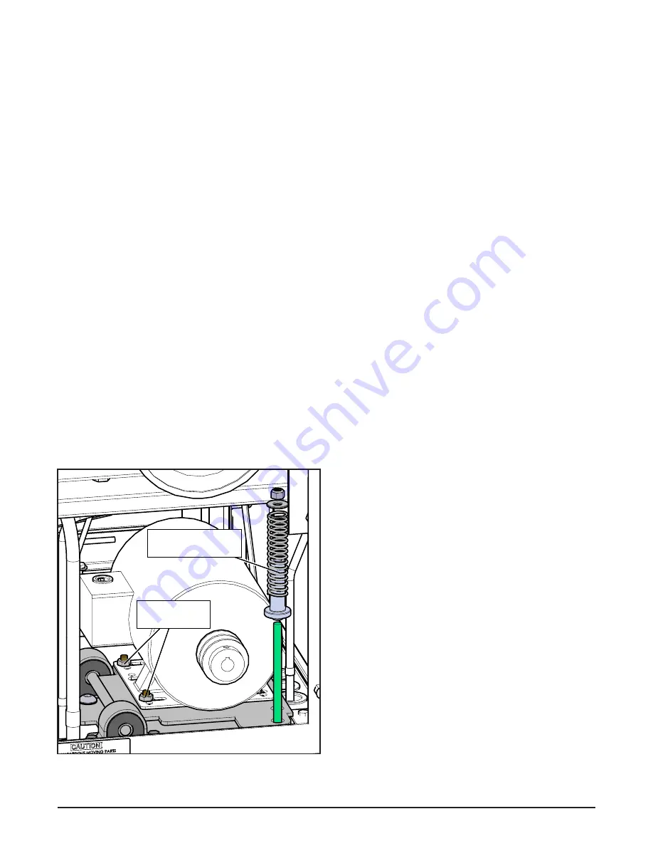
Remove the tensioning nut and tensioning
assembly. Then remove the belts. (Refer to Figure
3-2)
Figure 3-2 Motor Mounting Assembly
Remove motor
mounting nuts.
Remove tensioning
assembly.
Remove motor
mounting nuts.
Remove tensioning
assembly.
Summary of Contents for STOELTING U421-I2A
Page 1: ...Model U421 I2A U431 I2A SERVICE MANUAL Manual No 513721 Rev 0...
Page 2: ......
Page 44: ...Service Manual 513721 38 U421 I2A U431 I2A Model Machines...
Page 46: ...Service Manual 513721 40 U421 I2A U431 I2A Model Machines U421 48I2A 6 2 WIRING DIAGRAMS...
Page 47: ...Service Manual 513721 41 U421 I2A U431 I2A Model Machines U421 409I2A...
Page 48: ...Service Manual 513721 42 U421 I2A U431 I2A Model Machines U421 109I2A...
Page 49: ...Service Manual 513721 43 U421 I2A U431 I2A Model Machines U431 48I2A...
Page 50: ...Service Manual 513721 44 U421 I2A U431 I2A Model Machines U431 38I2A...
Page 51: ...Service Manual 513721 45 U421 I2A U431 I2A Model Machines U431 18I2A...
Page 52: ...Service Manual 513721 46 U421 I2A U431 I2A Model Machines U431 409I2A...
Page 53: ...Service Manual 513721 47 U421 I2A U431 I2A Model Machines U431 309I2A...
Page 54: ...Service Manual 513721 48 U421 I2A U431 I2A Model Machines U431 109I2A...


