Vollrath Stoelting SF121 I2 Operator'S Manual Download Page 12

Owner’s Manual #513677 

F144I2, SF144I2 and SF121I2 Model Machines

Help

Pressing the Help button will display help information 
dependant on the cursor’s location. Pressing the Help 
button again will exit the help screen.

Selection Button (SEL)

The SEL button is used by technicians to select menu 
options.

Set Button (SET)

The SET button is used by technicians to save changes 
when modifying control settings.

On/Off Button

Power to the freezing cylinders can then be controlled 
with the On/Off Left and On/Off Right switches.

Push to Freeze Button

Pressing the PUSH TO FREEZE button initiates “Serve 
Mode”.

Clean Button

The CLEAN button initiates “Clean Mode”.

Arrow Buttons (



)

The arrow buttons are used by technicians to navigate 
through the control readings and settings.

B. SPIGOT SWITCH

The spigot switch is mounted to the spigot cam assembly 
behind the header panel. When the spigot is opened to 
dispense product, the spigot switch opens and the “Serve 
Mode” begins.

C. DISPENSE RATE ADJUSTOR

The dispense rate adjustor is located under the header 
panel, to the immediate right of the spigot handles. Turning 
the knob counterclockwise will decrease the dispense rate.

D. BLENDER POWER SWITCH (SF144 MODELS ONLY)

The blender power switch is a two position toggle switch 
used to supply power to the blender. When the switch is 
in the OFF position, the agitator will not turn. When the 
switch is in the ON position, the agitator will be activated 
every time the blender activation switch is pressed. 

E. BLENDER ACTIVATION SWITCH

The blender activation switch is a two speed, momentary 
contact switch that will activate the agitator to blend prod-
uct when pressed and held. The HIGH speed position is 
used when blending product. The LOW speed position 
is used during cleaning procedures.

F. USB ACCESS PORT

The USB access port is located on the right side panel 
of the machine. The port is used by technicians to import 
fi rmware and export machine statistics.

3.3 DISASSEMBLY OF MACHINE PARTS

Before using the machine for the fi rst time, complete 
machine disassembly, cleaning and sanitizing proce-
dures need to be followed. Routine cleaning intervals 
and procedures must comply with the local and state 
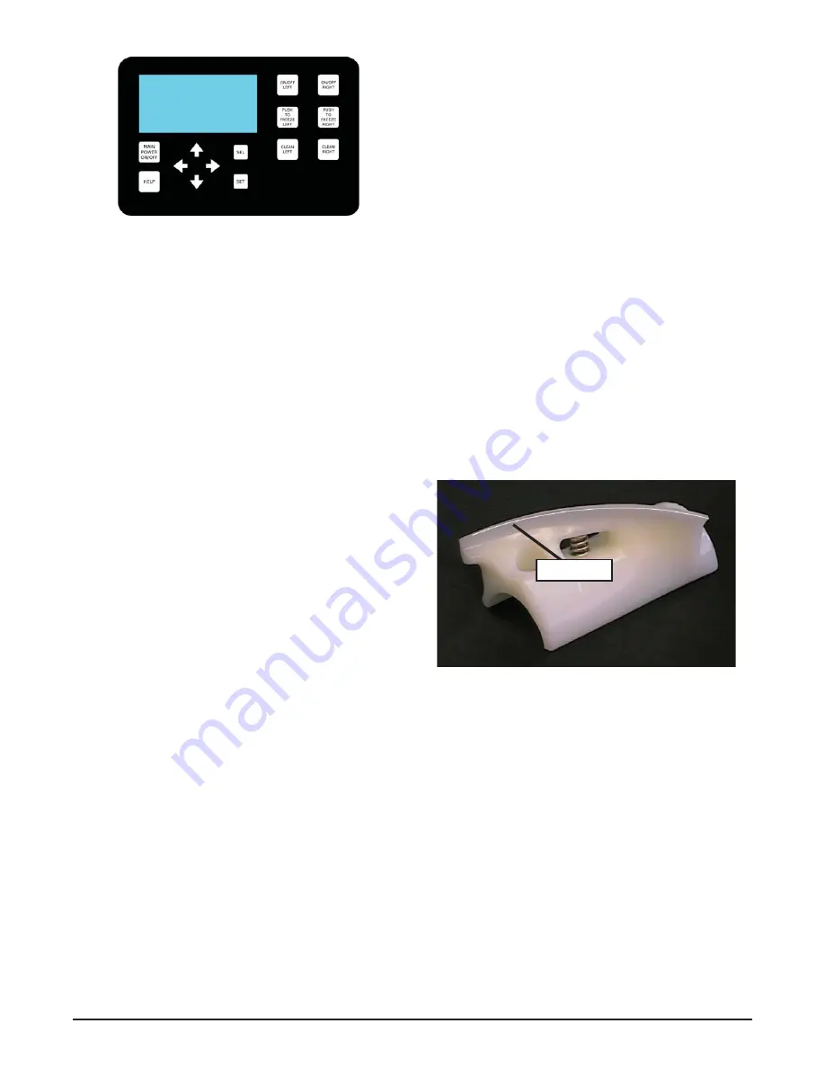
health codes. Inspection for worn or broken parts should 
be made at every disassembly of the machine. All worn 
or broken parts should be replaced to ensure safety to 
both the operator and the customer and to maintain good 
machine performance and a quality product. Check the 
wear line on the auger fl ights on a regular basis (Fig. 
3-3) and replace as needed. Frequency of cleaning must 
comply with the local health regulations.

To disassemble the machine, refer to the following steps:

A. REMOVING MIX

For the fi rst time cleaning the machine, skip to part
B. Disassembly of Front Door.

1. 

Press the Clean button. After mix has melted 
(about 5 minutes) open the spigot to drain the 
mix.

Fill the hopper with 2 gallons (8 liters) of cool tap 
water.

3. 

Press the Clean button to run the machine. After 
30 seconds press the Clean button again to stop 
the auger.

Figure 3-2 IntelliTec2™ Control

Wear Line

Figure 3-3 Auger Flight Wear

Summary of Contents for Stoelting SF121 I2

Page 1: ...Model SF144 I2 SF121 I2 OPERATORS MANUAL Manual No 513677 Rev 0...

Page 2: ......

Page 3: ...arts for freezers built prior to date of change DO NOT ATTEMPT to operate the machine until instructions and safety precautions in this manual are read completely and are thoroughly understood If prob...

Page 4: ...t specific safety information the following safety defini tions are provided to assist the reader The purpose of safety symbols is to attract your at tention to possible dangers The safety symbols and...

Page 5: ...sassembled Parts 8 3 5 Sanitizing Machine Parts 8 3 6 Cleaning the Machine 8 3 7 Assembling Machine 8 3 8 Sanitizing 9 3 9 Freeze Down and Operation 10 3 10 Fine Consistency Adjustment 11 3 11 Mix Inf...

Page 6: ......

Page 7: ...es a uniform product The machines are designed to operate with almost any type of commercial soft serve or non dairy mixes available including ice milk ice cream yogurt and frozen dietary desserts Thi...

Page 8: ...3 8 N P T water and drain fittings Hopper Volume Two 3 gallon 11 35 liters Freezing Cylinder Volume Two 0 85 gallon 3 22 liters Model SF121 I2 Dimensions Machine with crate width 22 55 9 cm 28 71 1 cm...

Page 9: ...carrier 2 3 MACHINE INSTALLATION WARNING Installation must be completed by a qualified electrician refrigeration specialist Incorrect installation may cause personal injury severe damage to the machi...

Page 10: ...Owner s Manual 513677 4 F144I2 SF144I2 and SF121I2 Model Machines...

Page 11: ...OPERATING CONTROLS AND INDICATORS Before operating the machine it is required that the op erator know the function of each operating control Refer to Figure 3 1 for the location of the operating cont...

Page 12: ...ivation switch is pressed E BLENDER ACTIVATION SWITCH The blender activation switch is a two speed momentary contact switch that will activate the agitator to blend prod uct when pressed and held The...

Page 13: ...chineoffbypressingtheMainFreezer Power Off On button on the IntelliTec2 control 2 Remove the knobs on the front door 3 Remove the front door by pulling it off the studs 4 Removethespigotthroughthebott...

Page 14: ...move and let air dry completely before assembling in machine 3 6 CLEANING THE MACHINE The exterior should be kept clean at all times to preserve the luster of the stainless steel A high grade of stain...

Page 15: ...d fit it into the groove on the rear of the front door M Place the front door assembly on the mounting studsandthepushfrontdooragainstthemachine carefully N Secure the front door to the machine by pla...

Page 16: ...5 gallons of mix D Place a container under the spigot and open the spigot to allow the mix to flush out about 8 ounces 0 23 liters of sanitizing solution and liquid mix E Press the On Off button for...

Page 17: ...e the changes Make adjustments in increments of 5 for best results 3 11 MIX INFORMATION Mix can vary considerably from one manufacturer to another Differences in the amount of butterfat content and qu...

Page 18: ...Owner s Manual 513677 12 F144I2 SF144I2 and SF121I2 Model Machines...

Page 19: ...ent in the area The water cooled condenser is a tube and shell type The condenser needs a cool clean supply of water to properly cool the machine inlet and discharge lines must be 3 8 I D minimum The...

Page 20: ...ghtsandaugersupportbushing in a plastic bag with a moist paper towel This will prevent them from becoming brittle if exposed to dry air over an extended period of time over 30 days D Forwater cooledma...

Page 21: ...when the compressor runs continuously for an extended period This error is generally caused by very low mix levels in the hopper or from product breakdown Another common cause results from a restrict...

Page 22: ...r proper flow from the water supply or kinks in the hoses If the error persists contact your Authorized Stoelting Distributor for further assistance Error Code 10 Auxiliary Sensor An Auxiliary Tempera...

Page 23: ...e 1 No mix in hopper 1 Add mix to the hopper 2 Drive motor overload tripped 2 Wait for automatic reset If condition continues call distributor for service 3 Drive belt failure 3 Replace drive belt 4 F...

Page 24: ...Owner s Manual 513677 18 F144I2 SF144I2 and SF121I2 Model Machines...

Page 25: ...ention Refrigerant Leak Check 1 324509 Decal Cleaning Instructions 1 324566 Decal Wired According To 1 324584 Decal Adequate Ventilation 3 3 324594 Decal Attention Heat Sensitive 4 324686 Decal Danger...

Page 26: ...13677 20 F144I2 SF144I2 and SF121I2 Model Machines 6 2 AUGER SHAFT AND FACEPLATE PARTS 3170644 149003 4157968 381804 694255 624678 5 666786 625133 2183047 2187812 624598 5 744271 744260 SV 744262 2149...

Page 27: ...24678 5 O Ring Rear Seal Black 5 Pack 2 625133 O Ring Front Door Red 2 666786 Seal Rear Auger Black 2 694255 Spring Auger Flight 8 744260 SV Tray Drip 1 744262 Tray Drain Black Plastic 1 744271 Insert...

Page 28: ...I2 and SF121I2 Model Machines Part Description Quantity 521026 Blender Agitator 1 522839 Blender Motor 1 674147 Blender Shaft 1 681514 Swing Shield Plastic 1 744299 Tray Drip Blender 1 6 3 BLENDER PAR...

Page 29: ...bligations remedies are subject to the conditions that Buyer a signs and returns to Stoelting upon installation the Checklist Warranty Registration Card for the affected equipment b gives Stoelting pr...

Reviews: