VOKERA AquaFlow Installation & Servicing Instructions Manual Download Page 7

Supplied By www.heating spares.co  Tel. 0161 620 6677

-6- 


taken to ensure the device is suitable for temperatures and fluids that may be present in a 

 solar-thermal 

system. 

 
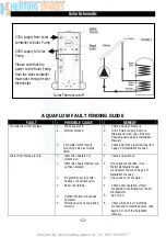
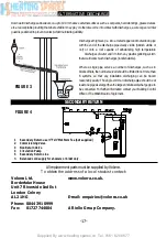
22.  Temperature sensors for the cylinder provided with the differential controller should be 
 

inserted into the pockets provided see figure 1A. 


COMMISSIONING 

 
Filling up 

1.  Open one hot water tap. 
2.  Close the commissioning valve (12). 
3.  Open the cold water supply valve. 
4.  When water flows from the open hot tap allow to flow to expel air from the system pipe work. 
5.  Open each hot water tap in turn to expel air from the system pipe work. 
6.  Check for leaks. 
7     Manually operate Temperature and Pressure Relief Valve (5) to ensure free water flow through 
discharge pipe.(Turn knob to left.) 
 

Draining 

Switch off the electrical power off (Important to avoid damage to element). Isolate boiler from 
Aquaflow unit. Turn off the cold water supply valve. Open hot water tap. Open drain (13). The unit 
will drain. 
 

SAFETY AND MAINTAINANCE 

Safety Cut-out 

1.  The safety cut-out operates if: 
 

a.  Wiring is incorrect. 


b.  The immersion heater thermostat or cylinder thermostat fails. 


c.  Thermostat is set too high. 

2.  Remember before resetting the safety cut-out or altering the thermostat setting, isolate 

electrical supply to the unit prior to removal of the electrical box lid. 

3.  Reduce thermostat setting and press the reset button. After adjustments are completed, ensure 

the lid to the electrical box is replaced correctly and the retaining screw is fitted. 

4.  If still out of operation, contact installer. 
 

Cold or tepid water discharge from tundish 

1.  Turn off the electrical supply to the immersion heaters. 
2.  Turn off cold water supply valve. 
3.  Open a hot tap. 
4.  Recharge the expansion vessel to the setting of the pressure reducing valve. 
5.  Close all hot taps. 
6.
  Open mains supply valve 

Summary of Contents for AquaFlow

Page 1: ...ions THESE INSTRUCTIONS TO BE RETAINED BY USER Vok ra is a licensed member of the Benchmark scheme which aims to improve the standards of installation and commissioning of domestic hot water systems i...

Page 2: ...nsporting or supporting of a load including the lifting putting down pushing pulling carrying or moving thereof by hand or bodily force The Regulations set no specific requirements such as weight limi...

Page 3: ...ock 250445 5 Temperature and Pressure Relief Valve 550803 14 Cable Entry 6 Tundish 219002 15 Electrical Box 7 Immersion Heater 71255 16 Tee Piece 250006 7A Thermostat Immersion Heater Thermostat Cylin...

Page 4: ...tting MI Drain Cock 250440 4 Check and Expansion Valve 510505 13 Elbow Drain Cock 250445 5 Temperature and Pressure Relief Valve 550803 14 Cable Entry 6 Tundish 219002 15 Electrical Box 7 7A Immersion...

Page 5: ...hose to the 1 2 outlet of the expansion valve 4 and the horizontal outlet of the tee piece see 5 above Discard compression nut ring 11 If a balanced mains pressure cold water supply is required to a...

Page 6: ...sion vessel to the cylinder as shown in the diagram below The vessel should be charged pressurised to the same pressure as the PRV Pressure Reducing Valve Solar Primaries 20 The Solar flow and return...

Page 7: ...oid damage to element Isolate boiler from Aquaflow unit Turn off the cold water supply valve Open hot water tap Open drain 13 The unit will drain SAFETY AND MAINTAINANCE Safety Cut out 1 The safety cu...

Page 8: ...of the body 4 The expansion valve should be either horizontal or upright if fitted inverted debris may be deposited on the seat and cause fouling of the seat when the valve operates Check direction of...

Page 9: ...Unscrew blue expansion relief headwork from valve body 3 Clean valve seat face and seating do not scratchordamageeithersealfaceorseating 4 Refit in reverse order Do not overtighten Expansion valve ca...

Page 10: ...t out is also incorporated within the thermostat and will operate at 85 C 3 C Should the safety cut out be brought into operation the motorised valve will operate and close down the primary flow to th...

Page 11: ...0161 620 6677 10 S Plan systems Refer to the wiring diagrams contained within the boiler installation instructions for the wiring of S Plan systems Connect the cylinder thermostat as shown in the dia...

Page 12: ...ng Layout Refer to the wiring diagrams contained within the boiler installation instructions for the wiring of Y Plan systems Connect the cylinder thermostat as shown in the diagram below NOTE A10wayj...

Page 13: ...Reducing Valve page 6 Installation Manual 3 Check and refit as required see item 3 page 5 of installation manual Water from hot taps is cold 1 Immersion heaters not switched on 2 Immersion heater the...

Page 14: ...check thermal controls replace if faulty Contact a competent person Continuous water discharge 1 Cold water inlet Pressure Reducing Valve not working 2 Temperature and pressure relief valve faulty 3 E...

Page 15: ...Supplied By www heating spares co Tel 0161 620 6677 14...

Page 16: ...Supplied By www heating spares co Tel 0161 620 6677 15...

Page 17: ...Supplied By www heating spares co Tel 0161 620 6677 16 Notes...

Page 18: ...umber of discharges such as in blocksofflats thenumberservedshouldbelimitedtonotmorethan 6 systems so that any installation discharging can be traced reasonably easily The single common dischargepipes...

Page 19: ...L2 1HG enquiries vokera co uk www vokera co uk www vokera ie Sales General Enquires T 0844 391 099 F 0844 391 0998 Vok ra Ireland West Court Callan Co Kilkenny T 056 7755057 F 056 7755060 Vok ra Limit...

Reviews: