Page 12 of 14
Manual Ikarray-8 - 2018-11 EN
Operation on tripod or spacer rod
max. load: two Ikarray-8 with tripod mechanics.
The Ikarray-8 Line Array is designed for flight and tripod operati
-
on. The flight and tripod mechanical parts are supplied with two
U-brackets. The U-bracket for tripod operation has a pre-assembled
threaded spindle for later fine adjustment of the inclination. Any
mount can be attached to this U-bracket to place the mechanism on
a tripod or spacer rod.
The second U-bracket is intended for flight operations and can be
equipped with a ring eye or traverse clamp, for example, to fly the
line array with the flight mechanics.
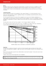
1. Fix the U-bracket at the foremost mounting point (A) of the
perforated rail with ball locking pins.
2. Fix threaded spindle with ball locking bolt (B).
3. Mount the connecting straps with ball lock pin (C).
4. Mount the holder for tripod/distance rod on the mechanics.
5. Place the loudspeaker on the mechanics and connect it with
ball lock bolts. Then connect the second speaker to the lower
speaker at the connection points.
Ikarray-8 in flight operation
max. load: four Ikarray-8 elements below each other.
1. Connect Ikarray-8 elements to each other.
2.
Mount the flight mechanism with ball lock pin (D).
3.
Align the flight mechanics by fixing the U-bracket on the upper
hole rail (E) with the ball locking bolt. How the center of gravity
behaves depends on the number of Ikarray-8 elements atta-
ched to the flight mechanics.
Note: For installations (e.g. on high ceilings) where the radiation
is particularly steep downwards, there is an optional extension
(F) of the perforated rail.
A
B
C
D
E
F
Working with Ikarray-8


