


Equipment
Description
2
5
D
K
G
n2
n1
a1
h1
h2
DN
1
f
a2
k
L
Ø
d
m1
m2
DN2
DNs
Dnd a1
f
h1 h2
m1
m2
n1
n2
S
d
l
50
50
4
260
80
5
125
462
200 260
380
320
27
27
45
115
6409
NU409
L
8
0
415
509
a2
k
397
80
125
260
462
200 260
50
50
380
320
45
115 NU409 7409 BECBJ
397
L80 3 and 4 Stages
215
270
125
5"
DN-1
DN
DN-2
80
3"
D
8
220
27
G
22
170
K
8
DIN 2535 (PN-40)
DIN 2546 (PN-64)
Figur
e
15
Tabl
e
13
Equipment
Description
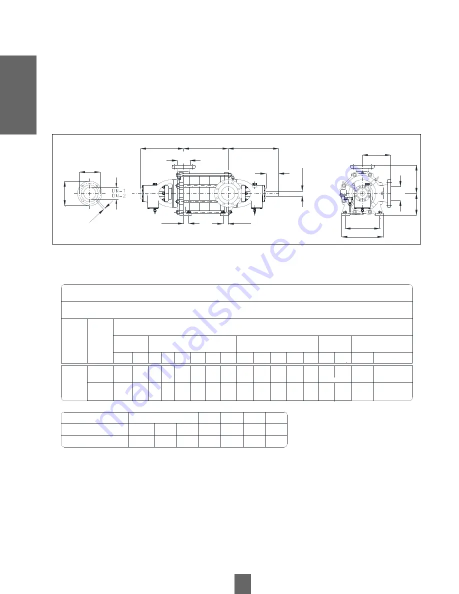
3.3.20
Dimensions of L Series Pumps, Model 80 4 and 5 stages
Model
s
Nodular Cast Iron Execution
Dimensions in Millimeters
No. of
Stages
Flanges
Pumps
Legs
Axis
Bearings
Suction
Download
Standard
Perf. qty.
Summary of Contents for L Series
Page 1: ......


