www.vogels.com
9531-060-Z05-00
1
3
2
4
13
13
12
11
Installation Guide
Installationsanleitung, Guía de Instalacíon, Guida de Installazione, Guide d’Installation, Installatie gids
PFT8857
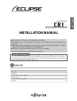
5/32”
CL
5/32”
With the display safely positioned “face down” on a smooth
flat surface place the cross bar with brackets loosely at-
tached so the center of the round receiver is center on the
display left to right and top to bottom.
Slide the left and right mounting bracket over the left and
right mounting holes (normally four each) and firmly install
the brackets to the display with the correct length M8 x 1.25
Phillips head screw supplied. Note: measure the depth of
the threaded mounting hole to confirm the correct length of
the M8 screws from the three lengths supplied Confirm the
crossbar is still centered left to right on the rear of the dis-
play and firmly secure the bracket to the cross bar with the
four M6 x 1.0 x 10mm Allen head set screws supplied.
Eight optional use M4 - M8 plastic spacer are included in
the hardware kit if needed to create clearance between the
mounting g bracket and the display. These
spacers easily joined together for additional height is
needed as well.
Slide the left and right display mounting brackets over the
cross bar and install the left and right M6 x 1.0 x 12mm se-
curity Phillips head screws supplied into the cross bar.