background image

8

Descriptions and Functions

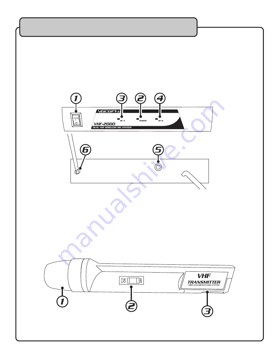
RECEIVER

1.  Power Switch

 - This powers the receiver ON/OFF .

2.  Power LED

 - This indicates power to the receiver .

3.  RF A - 

This LED registers the connection of Microphone A .

4.  RF B

 - This LED registers the connection of Microphone B .

5.  Audio Output

 - This 1/4” jack outputs both microphones’ audio .

6.  Antenna

 - Fully extend the antenna for best reception .

MICROPHONES

1.  Mic Head

 - This portion of the mic picks up the vocal audio .

2.  Power/Mute Switch

 - This LED indicates power ON/OFF and Low Battery .  

a . Middle Position - Mutes the mic without shutting it off . 

b . When powered on, this LED will flash and go out quickly . 

c . When the battery is low, this LED will be on continuously .

3.  Battery Compartment

 - This is where the 9V battery is installed . 

Front

AUDIO OUT

ANT.

Back

Summary of Contents for VHF-2000

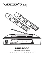
Page 1: ...VHF 2000 Wireless Microphone System o w n e r s m a n u a l...

Page 2: ...2 Table of Contents Safety Instructions 3 FCC Information 4 Welcome 5 Listening for a Lifetime 6 Before Getting Started 7 Descriptions and Functions 8 Getting Connected 9 Commonly Asked Questions 10...

Page 3: ...nces including amplifiers that produce heat 10 Power Sources The appliance should be connected to a power supply only of the type described in the operating instructions or as marked on the appliance...

Page 4: ...ce for future reference 2 Install your unit in a cool dry clean place away from windows heat sources and too much vibration dust moisture or cold Avoid sources of hum transformers electric motors To p...

Page 5: ...Curtiss Court La Verne CA 91750 Toll Free 800 678 5348 TEL 909 593 8893 FAX 909 593 8890 VocoPro Company Email Directory Customer Service General Information info vocopro com Tech Support techsupport...

Page 6: ...ay attention to the different levels in various recordings Taking a minute to do this now will help to prevent hearing damage or loss in the future After all we want you listening for a lifetime Used...

Page 7: ...nes Plug Play Design No Advanced Setup Required Wireless Range of 80ft Microphones Use 9V Batteries Rechargeable Batteries OK Includes Single Unbalanced 1 4 Microphone Cable WHAT S IN THE BOX VHF 2000...

Page 8: ...uts both microphones audio 6 Antenna Fully extend the antenna for best reception MICROPHONES 1 Mic Head This portion of the mic picks up the vocal audio 2 Power Mute Switch This LED indicates power ON...

Page 9: ...the VHF 2000 Receiver 2 Plug in the included 1 4 to 1 4 mono patch cable into the Audio Output 3 Plug the other end of the 1 4 to 1 4 mono patch cable into a microphone input on either a mixer amplif...

Page 10: ...unication issues 3 Q Will this unit interfere with other wireless microphone systems I have So long as the operational frequency does not match with any other microphone system being used there will b...

Page 11: ...11 Notes...

Page 12: ...VHF 2000 Owner s Manual VocoPro 2015 v1 0320 www vocopro com...

Reviews: