background image

DMI-64

POWER

COM

MARK II

2

4

3

5

PARAMETER  VALUE

PRESET

1

PRESET/PARAMETER 

VALUE 

USING THE DMI-64 MARK II

Front Panel

On the front of the DMI-64 II you will find the following:

1. POWER SWITCH - push on/push off

2. POWER/COMMUNICATIONS INDICATOR LED - This is a multipurpose

indicator.  The indicator will light a green color when power is applied to the

unit, except when the unit is operating in EDIT MODE (refer to section 2 of

this manual for a description of EDIT MODE), in which case the indicator will

be red.  When MIDI information is being transmitted (i.e. when you press or

release a key on a keyboard), the indicator will flash from GREEN to RED or

from RED to GREEN depending on whether you're in normal play mode or

EDIT MODE respectively.

3. Increment and Decrement buttons for changing preset or Edit Mode

parameter number.

4. Four digit LCD display - This is a multipurpose display used for the following

functions:

I - Display preset selection for the basic MIDI channel

II - Display programming parameters in EDIT MODE

5. Increment and Decrement buttons used only in Edit Mode to change a

parameter's value.

1-2

Summary of Contents for DMI-64 Mark II

Page 1: ...DMI 64 MARK II USER S MANUAL 111 Tenth Street Wood Ridge NJ 07075 201 939 0052 ...

Page 2: ...ing up the DMI 64 Mark II 1 6 Playing the DMI 64 Mark II 1 6 Taking Care of the DMI 64 Mark II 1 7 Section 2 PROGRAMMING THE DMI 64 MARK II Editing Parameters 2 1 Parameter Information 2 3 Appendix A FACTORY PRESETS TABLE Appendix B MIDI SYSTEM EXCLUSIVE INFORMATION Appendix C DMI 64 MARK II SPECIFICATIONS Appendix D CHANGING THE BATTERY IN THE DMI 64 MARK II WARRANTY ManualRev 3 2 DMI 64 Mark II ...

Page 3: ... map and keyboard split settings The unit also includes 64 factory programed waveforms These presets will allow the user to begin playing the DMI 64 II right out of the box without having to do any programming If necessary any or all of the 99 preset programs may be altered by using the built in Edit Mode or the DMI 64 II Soft Control software Eight of the 64 waveforms can be modified by the built...

Page 4: ...e following items 1 DMI 64 II User s Manual 2 External AC adaptor 3 MIDI Implementation Chart 4 Parameter Chart 5 Rubber Feet NOTE Save the DMI 64 II s packing carton For carrying and shipping it provides the best protection short of a hard case DMI 64 Mark II User s Manual 1 1 ...

Page 5: ...n of EDIT MODE in which case the indicator will be red When MIDI information is being transmitted i e when you press or release a key on a keyboard the indicator will flash from GREEN to RED or from RED to GREEN depending on whether you re in normal play mode or EDIT MODE respectively 3 Increment and Decrement buttons for changing preset or Edit Mode parameter number 4 Four digit LCD display This ...

Page 6: ...NCED AUDIO CONNECTORS These are 1 4 inch phone jacks for connecting the DMI 64 II to an instrument amplifier 3 MIDI IN OUT THRU DIN CONNECTORS These are the connectors used for connection to other MIDI devices The DMI 64 II functions in accordance with the IMA MIDI standard 4 AC CONNECTOR This connector is for supplying power to the DMI 64 II It mates to a matching connector on the AC adaptor prov...

Page 7: ... controller Connect the other end of the cable to the MIDI IN port of your DMI 64 II Step 2 is optional Step 2 If you are using the MIDI controller with more than one MIDI instrument in your MIDI setup you can use the DMI 64 II s MIDI THRU port to connect to the next MIDI instrument You can do this by connecting one end of a MIDI cable to the MIDI THRU port on the DMI 64 II Connect the other end o...

Page 8: ...64 II A preset may be setup to play on only Audio Channel 1 Audio Channel 2 on both Mono or on both Stereo The former modes are useful when using a split program or multitimbral mode For example a split program may have the preset active below a certain MIDI note assigned to Audio Channel 1 while the upper preset may be assigned to the other audio channel The latter mode Stereo may be used with th...

Page 9: ... II begins to flash This means that the DMI 64 II is receiving MIDI information from your keyboard and that you should be hearing audio Adjust the volume to a comfortable level and begin to play You may change the preset the DMI 64 II is sounding by using the leftmost In crement and Decrement buttons when not in EDIT MODE You will notice that the two digits on the display represent the preset numb...

Page 10: ...waveforms This battery should provide up to 4 years of backup Should it become necessary to replace the battery see your dealer or contact Voce Inc for a replacement battery or for information on where to obtain one The following is a list of replacement batteries Sanyo 2340 270 mA Hr Panasonic BR2330 250 mA Hr You may replace the battery by either bringing it to your dealer or you can do it yours...

Page 11: ...egories Waveform Select Effects MIDI Controller Map Pitch and Volume offsets Audio Channel Assignment Channel Split Waveform Generation MIDI System Exclusive Dumps and Mul titimbral Channel Selects There are 64 waveforms available for use in the DMI 64 II The last 8 of these waveforms 56 63 are programmable by the user The method provided in Edit Mode for creating waveforms is an additive one simi...

Page 12: ...er to create different timbres for different ranges of notes A sustain hold function is availible on the DMI 64 II This allow the user to hold chords while playing other keyboard Parameter 83 is used to selected the MIDI control number for this function The user may re initilize the DMI 64 II to the factory presets by using parameter 84 This will return the unit s memory to the state which it was ...

Page 13: ...aveform used by the digital voice os cillators Value Range 00 63 Actual Value 0 63 04 Distortion activates analog distortion circuitry This effect is global for the entire audio output of the instrument it is important to remember this when the effect is used in multitimbral setups or split programs Value Range 00 01 Actual Value 00 Overdrive Off 01 Over drive On 05 Volume used to adjust volume of...

Page 14: ...t Depth Sw Off Depth Sw Off Rate Sw Off Rate Sw Off Depth Sw Off Rate Sw Off Rotating Speaker Effect No frequency mod effect Depth Sw On Rate Sw Off Vibrato Effect Chorus Effect Depth Sw On Depth Sw On Rate Sw Off Rate Sw Off Depth Sw On Rate Sw Off Rotating Speaker Effect No frequency mod effect Depth Sw Off Rate Sw On Vibrato Effect Chorus Effect Depth Sw Off Depth Sw Off Rate Sw On Rate Sw On D...

Page 15: ...n Percussion On Perc Decay On Perc Decay Off Perc Decay On Perc Decay Off Perc Decay On Perc Decay Off Perc Decay On Perc Decay Off Perc Decay On Perc Decay Off Perc Decay On Perc Decay Off Perc Decay On Perc Decay Off Perc Decay On Perc Vol Off Perc Vol On Perc Vol On Perc Vol Off Perc Vol Off Perc Vol On Perc Vol On Perc Vol Off Perc Vol Off Perc Vol On Perc Vol On Perc Vol Off Perc Vol Off Perc...

Page 16: ...ate Sw En Rate Sw En Rate Sw En Parameter 11 Value Virtual Switch Enables En Enabled Ne Not Enabled 00 01 02 03 04 05 06 07 08 09 10 11 12 13 14 15 Perc Wave Sel Ne Percussion Ne Perc Vol Ne Perc Decay Ne Percussion Ne Percussion Ne Percussion Ne Percussion Ne Percussion Ne Percussion Ne Percussion Ne Percussion En Percussion En Percussion En Percussion En Percussion En Percussion En Percussion En...

Page 17: ... amount of vibrato effect produced when the Depth Select control switch is deactivated Value Range 00 03 Actual Value 00 most shallow 03 deepest 17 Vibrato Depth control switch on amount of vibrato effect produced when the control switch is activated Value Range 00 03 Actual Value 00 most shallow 03 deepest 18 Chorus Depth control switch off amount of chorus effect produced when the Depth Select c...

Page 18: ...6 Percussion Volume control switch off selects the percussion volume to be used when the Percussion Volume Select control switch is deactivated Value Range 00 63 Actual Value 00 Softest 63 Loudest 27 Percussion Volume control switch on selects the percussion volume to be used when the Percussion Volume Select control switch is deactivated Value Range 00 63 Actual Value 00 Softest 63 Loudest 28 Per...

Page 19: ...troller assignment for Rotating Speaker On control switch Value Range 00 99 Actual Value 99 Channel Pressure 0 98 MIDI Control 35 Vibrato MIDI Control Switch MIDI controller assignment for Vibrato On control switch Value Range 00 99 Actual Value 99 Channel Pressure 0 98 MIDI Control 36 Chorus MIDI Control Switch MIDI controller assignment for Chorus On control switch Value Range 00 99 Actual Value...

Page 20: ...hannel Pressure 0 98 MIDI Control 41 Perc Volume MIDI Control Switch MIDI controller assignment for Per cussion Volume Select control switch Value Range 00 99 Actual Value 99 Channel Pressure 0 98 MIDI Control 42 Perc Waveform MIDI Control Switch MIDI controller assignment for Percussion Waveform Select control switch Value Range 00 99 Actual Value 99 Channel Pressure 0 98 MIDI Control 43 Distorti...

Page 21: ...monic 1 amplitude value for the 1st harmonic wave Corresponds to the 1st drawbar of a tone wheel organ Value Range 00 08 Actual Value 0 8 46 Waveform Generation Harmonic 3 corresponds to the 2nd drawbar of a tone wheel organ Value Range 00 08 Actual Value 0 8 47 Waveform Generation Harmonic 2 corresponds to the 3rd drawbar of a tone wheel organ Value Range 00 08 Actual Value 0 8 48 Waveform Genera...

Page 22: ...ent preset with data from the selected preset parameter 54 Value Range 00 03 03 Do Copy Function 56 Send MIDI Patch Dump dumps MIDI System Exclusive data correspond ing to the selected preset through the MIDI OUT port Parameters 2 through and including 43 or parameters 2 through and including 53 if a programmable waveform 56 63 is selected are sent Activated by Value Increment button 57 Send MIDI ...

Page 23: ...annel The basic chan nel cannot be turned off Value Range 00 99 Actual Value 0 channel off 1 99 are presets 1 99 62 Channel 4 Preset Number the preset active for play on MIDI Channel 4 Changes to this parameter may change the preset you are editing because you are editing the current preset selected for the basic channel The basic chan nel cannot be turned off Value Range 00 99 Actual Value 0 chan...

Page 24: ...the basic channel The basic chan nel cannot be turned off Value Range 00 99 Actual Value 0 channel off 1 99 are presets 1 99 68 Channel 10 Preset Number the preset active for play on MIDI Channel 10 Changes to this parameter may change the preset you are editing because you are editing the current preset selected for the basic channel The basic chan nel cannot be turned off Value Range 00 99 Actua...

Page 25: ...parameter may change the preset you are editing because you are editing the current preset selected for the basic channel The basic chan nel cannot be turned off Value Range 00 99 Actual Value 0 channel off 1 99 are presets 1 99 74 Channel 16 Preset Number the preset active for play on MIDI Channel 16 Changes to this parameter may change the preset you are editing because you are editing the curre...

Page 26: ...bove Useful for simulating the har monic foldback of tone wheel organs in which the timbre changes over the note range Value Range 00 63 Actual Value 0 63 80 Zone 5 Waveform selects the waveform used by the digital voice oscil lators for note range shown in the chart above Useful for simulating the har monic foldback of tone wheel organs in which the timbre changes over the note range Value Range ...

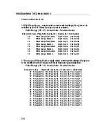
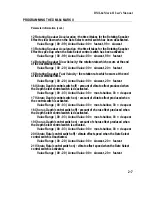
Page 27: ... Control MIDI controller assignment for hold func tion Value Range 00 98 Actual Value 0 98 84 Re initialize to Factory Presets by incrementing this parameter to 99 The DMI will be restored to the factory state Value Range 00 99 Actual Value 0 99 DMI 64 Mark II User s Manual 2 17 ...

Page 28: ...pkr Slow N A Stereo 15 Fast Voxx 51 Full Voxx Fast Vibrato N A Stereo 16 Fast Farf 52 Full Farf Fast Vibrato N A Stereo 17 Voxx 16 53 Voxx 1 No Effect N A Stereo 18 Farf 16 54 Farf 1 No Effect N A Stereo 19 Slow Joey 2 57 Joey 2 888800008 Rot Spkr Slow N A Stereo 20 Slow Rock 2 61 Rock 2 808760040 Rot Spkr Slow N A Stereo 21 J Smith 01 Jazz 888000000 Fast Chorus Perc 3 N A Mono 22 Chorus Church 03...

Page 29: ... Dist 48 Dist Slow Bass 1 33 Bass 1 808000000 Rot Spkr Slow N A Stereo Dist 49 Dist Slow Hollow 35 Hollow 880080550 Rot Spkr Slow N A Stereo Dist 50 Dist Slow Cool 1 40 Cool 1 888008000 Rot Spkr Slow N A Stereo Dist 51 Dist Slow Cool 2 43 Cool 2 846040500 Rot Spkr Slow N A Stereo Dist 52 Dist Slow Cool 3 47 Cool 3 800800000 Rot Spkr Slow N A Stereo Dist 53 Dist Slow Vibe 48 Vibe 800000000 Rot Spkr...

Page 30: ...k 2 808760040 Fast Chorus Note 60 Channel 1 81 Dist J Smith 01 Jazz 888000000 Fast Chorus Perc 3 N A Mono Dist 82 Dist Chrs Church 03 Church 808808008 Fast Chorus N A Mono Dist 83 Dist Chrs Full 07 Full 888888888 Fast Chorus N A Mono Dist 84 Dist Chrs Joey 1 14 Joey 1 888800000 Fast Chorus Perc 3 N A Mono Dist 85 Dist Chrs Yes 16 Yes 888473256 Fast Chorus N A Mono Dist 86 Dist Chrs Rock 1 23 Rock ...

Page 31: ...able waveform 56 63 is used MIDI SAMPLE DUMP INFORMATION 1 The DMI 64 Mark II will transmit any or its internal waveforms but will only accept samples for waveform numbers 56 though 63 2 Sample number must be set to the desired waveform number Channel number must be set to the Basic Channel number 1 3 The sample loop start point must be set to the beginning of a 256 point loop by the preset Append...

Page 32: ...ally WAVEFORMS 64 factory waveforms 8 of which are reprogrammable PROGRAMS 99 user reprogram mable presets TUNING 3 125 cents resolution EFFECTS Rotating speaker vibrato chorus tone wheel organ percussion distortion key click and hum CONTROL FUNCTIONS Effect rate fast slow effect depth low high tone wheel organ percussion volume decay and waveform rotating speaker select vibrato select chorus sele...

Page 33: ...ery on the front left hand corner of the DMI 64 II s printed circuit board Remove the battery by lifting one end of the battery retaining clip with one hand while at the same time sliding it out of the holder with the other hand Step 4 Insert the new battery in the reverse order of Step 3 making sure that the positive side of the battery is up Step 5 Replace top panel and refasten the screws Recon...

Page 34: ...MITATION OF IMPLIED WARRANTIES ALL IMPLIED WARRANTIES INCLUDING WARRANTIES OF MERCHANTABILITY AND FITNESS FOR A PARTICULAR PURPOSE ARE LIMITED IN DURATION TO THE LENGTH OF THIS WARRANTY EXCLUSION OF DAMAGES VOCE S LIABILITY FOR ANY DEFECTIVE PRODUCT IS LIMITED TO THE REPAIR OR REPLACEMENT OF THE PRODUCT AT OUR OPTION VOCE SHALL NOT BE LIABLE FOR 1 DAMAGE TO OTHER PROPERTY CAUSED BY ANY DEFECTS IN ...

Reviews: