


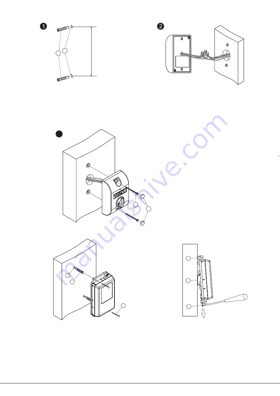
- Make measurements on a wall with center
to center distance 60 mm.
Drill 2 holes (1) with diameter 6 mm and
depth 30 mm.
- Drive anchors (2) in the holes.
2
60 mm
1
- Connect the Reader’s RD-3 wires
to wires of the control unit KTM600M
and button EXIT-300M following the
diagrams given in the section
.
EXAMPLES
OF WIRING DIAGRAMS
READER RD-3
INSTALLATION
3
- Attach the Reader RD-3 to the wall and
fasten two screws
in the anchors.
- Drive in gags
Anchors, screws and gags are supplied
with VIZIT-KTM600R
3.5х30 (3)
(4).
.
3
4
- Drill in a wall 2 holes (1) with diameter 6 mm
and depth 30 mm
- Drive anchors (2) in the holes
Attach the control unit to the wall and fasten
screws
25
in the anchors
Anchors and screws are supplied with
VIZIT-KTM600R
.
.
-
2
3.5х
(3)
.
.
CONTROL UNIT KTM600M
INSTALLATION
1
2
3
-
- DI -
35
1-2
-
Bosses on the control unit’s base
rail with width
mm and
thickness
mm
Holder for fixing
N
1
2
3
1
2
3
KTM600M mounting on a
rail
DIN-
KTM600M mounting on a wall
www.vizit.eu
VIZIT-КТМ600R
2/6
OPERATING INSTRUCTION


