background image

EN-7

English

1. Install the "Installation Wizard 2" from the Software Utility directory on the software 

CD.

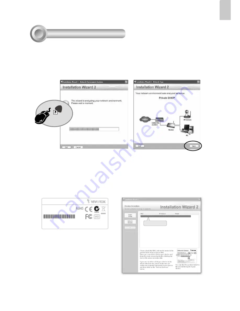
2. The program will conduct an analysis of your network environment. After your network 

is analyzed, please click on the "Next" button to continue the program.

3. The program will search for VIVOTEK Video Receivers, Video Servers or Network 

Cameras on the same LAN.

4. After a brief search, the main installer window will pop up. Double-click on the MAC 

address that matches the one printed on the camera label or the S/N number on the 

package box label to open a browser management session with the Network Camera.

Installation

Wizard 2

IW

2

Assigning an IP Address

5

Network Camera

Model No: IP8331

Made in Taiwan

This device complies with part 15 of the FCC rules. Operation is subject to the following two conditions: 
(1)This device may not cause harmful interference, and 
(2) this device must accept any interference received, including interference that may cause undesired operation.

Pat. 6,930,709

RoHS

MAC:0002D1730202

0002D1730202

00-02-D1-73-02-02                192.168.5.151                 IP8331

Summary of Contents for IP8331

Page 1: ......

Page 2: ... manual for the operating temperature Power off the Network Camera as soon as smoke or unusual odors are detected Do not touch the Network Camera during a lightning storm Do not place the Network Camera on unsteady surfaces Do not drop the Network Camera Do not insert sharp or tiny objects into the Network Camera ...

Page 3: ...age Contents 1 510000202G Software CD IP8331 RJ45 Female Female Coupler Quick Installation Guide Warranty Card Camera Stand Power Adapter Moisture Absorber Silica gel Waterproof Connector 3 Holes for Backup Use ...

Page 4: ...EN 3 English Physical Description 2 Connectors Ethernet 10 100 RJ45 Plug Power Cord Socket Black General I O Terminal Block Front Panel IR LED Lens Reset Button Status LED Light Sensor Back Panel ...

Page 5: ...r installation 4 Make sure all cable lines are securely connected 5 Tighten the back cover rubber and waterproof connector 6 Secure the Network Camera to the wall ceiling by the supplied camera stand 1 2 3 Silica gel 6 5 Ceiling Mount Wall Mount Note If you want to use your own cable lines please loose two supplied screws and take out the power board Then be careful to make connections as the illu...

Page 6: ...rom general I O terminal block 2 Use the supplied RJ45 female female coupler to connect the Network Camera to a switch Use a Category 5 Cross Cable when your network camera is directly connected to PC 3 Connect the power cable from the Network Camera to a power outlet AC24V 24V AC24V 24V D I Digital Input GND Ground AC24V AC24V DI GND General Connection without PoE ...

Page 7: ... switch The Network Camera is PoE compliant allowing transmission of power and data via single Ethernet cable Follow the below illustration to connect the Network Camera to a PoE enabled switch via Ethernet cable POWE R COLLIS ION LINK R E CE IVE PAR TITION 1 2 3 4 5 Non PoE Switch PoE Power Injector optional POWE R COLLIS ION LINK R E CE IVE PAR TITION 1 2 3 4 5 PoE Switch ...

Page 8: ...click on the MAC address that matches the one printed on the camera label or the S N number on the package box label to open a browser management session with the Network Camera Installation Wizard 2 IW2 Assigning an IP Address 5 Network Camera Model No IP8331 Made in Taiwan This device complies with part 15 of the FCC rules Operation is subject to the following two conditions 1 This device may no...

Page 9: ...sion with the Network Camera should prompt as shown below 2 You should be able to see live video from your camera You may also install the 32 channel recording software from the software CD in a deployment consisting of multiple cameras For its installation details please refer to its related documents ...

Page 10: ......

Reviews: