EN - 5
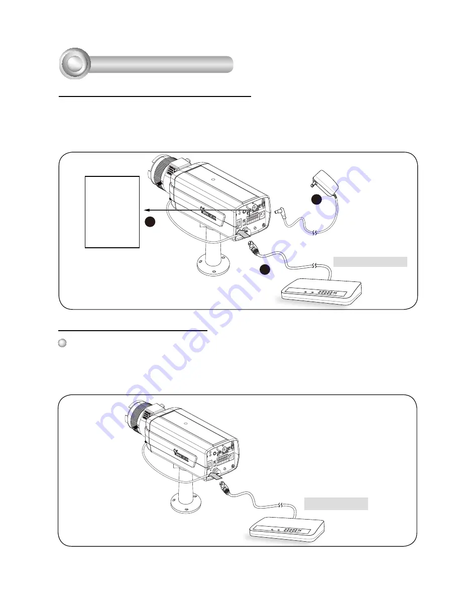
General Connection (without PoE)
1. If you have external devices such as sensors and alarms, connect them to the
general I/O terminal block.
2. Connect the camera to a switch via Ethernet cable.
3. Connect the power cable from the Network Camera to a power outlet.
1
2
3
POWER
COLLISION
LINK
RECEIVE
PARTITION
1
2
3
4
5
4
Network Deployment
Ethernet Switch
1: Power +12V
2: Digital output
3: Digital input
4: Ground
5: AC 24V
6: AC 24V
7: RS485+
8: RS485-
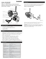
Power over Ethernet (PoE)
When using a PoE-enabled switch
The Network Camera is PoE-compliant, allowing transmission of power and data via
a single Ethernet cable. Follow the below illustration to connect the Network Camera
to a PoE-enabled switch via Ethernet cable.
POWER
COLLISION
LINK
RECEIVE
PARTITION
1
2
3
4
5
PoE Switch


