


EN - 7
English
Network Camera
Model No: IP8151P
Made in Taiwan
This device complies with part 15 of the FCC rules. Operation is subject to the following two conditions:
(1)This device may not cause harmful interference, and
(2) this device must accept any interference received, including interference that may cause undesired operation.
Pat. 6,930,709
MAC:0002D1730202
Ro HS
0002D1730202
00-02-D1-73-02-02 192.168.5.151 IP8151
Installation
Wizard 2
IW
2
5
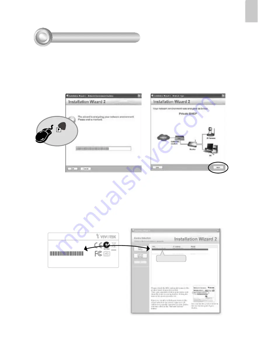
Assigning an IP Address
1. Install "Installation Wizard 2" from the Software Utility directory on the software CD.
2. The program will conduct an analysis of your network environment. After your network
is analyzed, please click on the "Next" button to continue the program.
3. The program will search for VIVOTEK Video Receivers, Video Servers, and Network
Cameras on the same LAN.
4. After searching, the main installer window will pop up. Click on the MAC that matches
the one labeled on the bottom of your device to connect to the Network Camera via
Internet Explorer.


