4
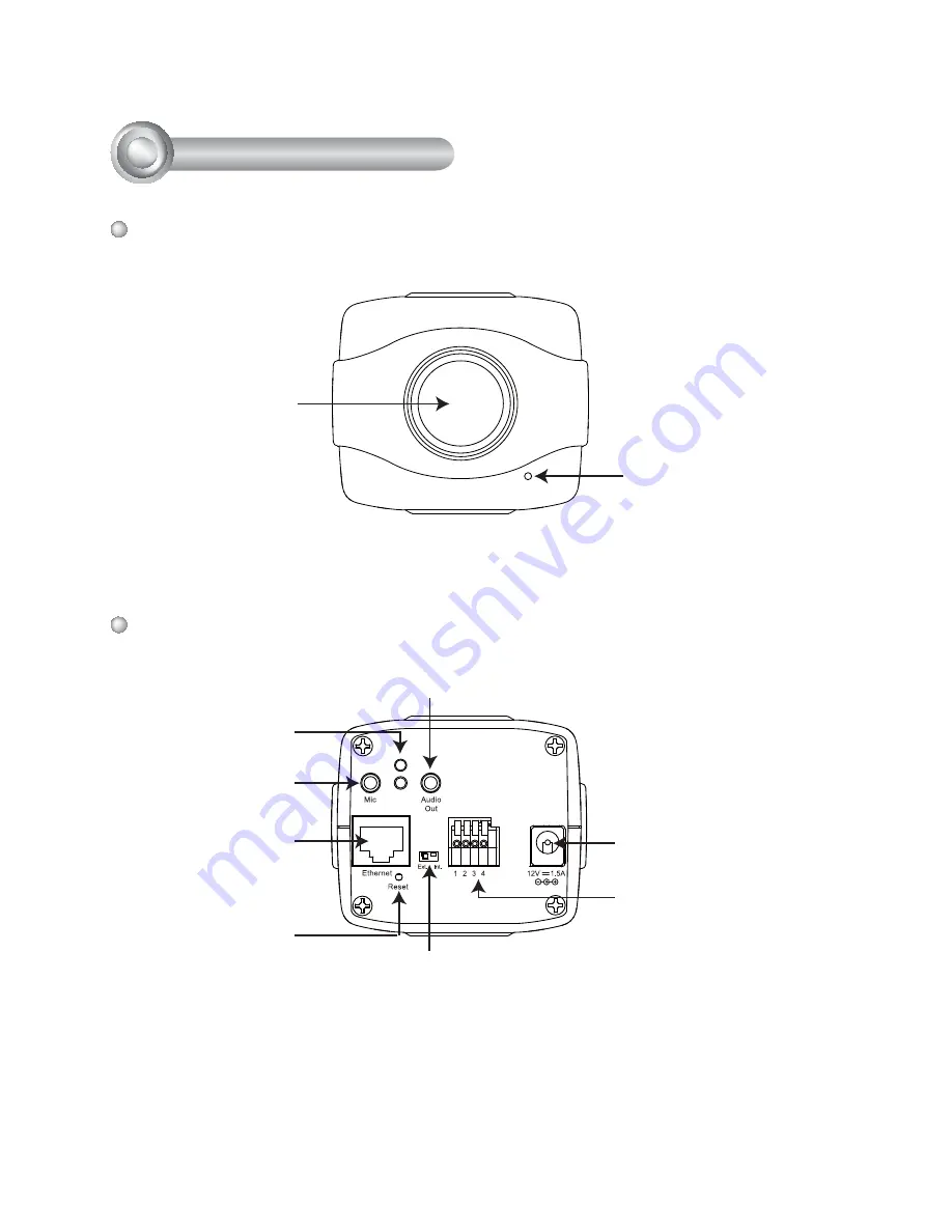
Power Cord Socket
Ethernet 10/100
RJ45 Socket
Indented Reset
Button
General I/O Terminal Block
Audio Out
External/Internal MIC Switch
Microphone In
Front Panel
Back Panel
2
Physical Description
Built-in Microphone
Status LED
Lens
Page 1: ......
Page 2: ...nual for the operating temperature Power off the Network Camera as soon as smoke or unusual odors are detected Do not place the Network Camera around heat sources such as a television or oven Keep the Network Camera away from direct sunlight Do not place the Network Camera in high humidity environments Contact your distributor in the event of occurrence Warning Before Installation ...
Page 3: ...Network Camera on unsteady surfaces Do not touch the Network Camera during a lightning storm Do not disassemble the Network Camera Do not drop the Network Camera Do not insert sharp or tiny objects into the Network Camera ...
Page 4: ...3 English Camera Stand Software CD IP7130 Power Adapter Quick Installation Guide Warranty Card 1 Package Contents ...
Page 5: ...cket Ethernet 10 100 RJ45 Socket Indented Reset Button General I O Terminal Block Audio Out External Internal MIC Switch Microphone In Front Panel Back Panel 2 Physical Description Built in Microphone Status LED Lens ...
Page 6: ...hem to the general I O terminal block 2 Connect the camera to a switch via Ethernet cable 3 Connect the supplied power cable from the camera to a power outlet 1 2 3 POWE R COLLIS ION LINK R E CE IVE PAR TITION 1 2 3 4 5 3 Network Deployment Ethernet Switch 1 Power 12V 2 Digital output 3 Digital input 4 Ground ...
Page 7: ...R E CE IVE PAR TITION 1 2 3 4 5 When using a PoE enabled switch This Network Camera is PoE compliant allowing transmission of power and data via a single Ethernet cable Follow the below illustration to connect the camera to a PoE enabled switch via Ethernet cable POWE R COLLIS ION LINK R E CE IVE PAR TITION 1 2 3 4 5 PoE Switch Non PoE Switch PoE Power Injector optional ...
Page 8: ...8 5 151 IP7130 Installation Wizard 2 IW2 4 Assigning an IP Address 1 Install Installation Wizard 2 from the Software Utility directory on the software CD 2 The program will conduct an analysis of your network environment After your network is analyzed please click on the Next button to continue the program 3 The program will search for VIVOTEK Video Receivers Video Servers and Network Cameras on t...
Page 9: ...8 For further setup please refer to the user s manual on the software CD Ready to Use 5 1 Access the Network Camera on the LAN 2 Retrieve live video through a web browser or recording software ...
Page 10: ......