background image

12 


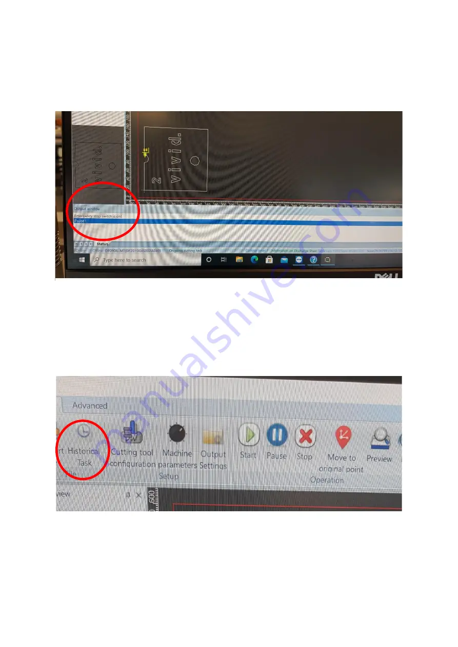
At the bottom of the screen is the Output window [Figure 4.4], this gives the 
information of any errors, if the machine is in run/pause mode and or if the 
emergency stop buttons are pressed. 


The Historic tasks button on the top left of the screen [Figure 4.5], saves 
previous cut files that have been used. When restoring a file, right click the file 
and press restore. Please note these files cannot be edited and can only be 
used in Direct cut mode. 


Figure 4.4


Figure 4.5 

Summary of Contents for Veloblade Volta

Page 1: ...0 Introduction User Manual for...

Page 2: ...Chapter 2 Tools and their positions Page 6 10 Chapter 3 Tool settings Test Depth Page 11 15 Chapter 4 Software lay out Page 16 Chapter 5 Importing files Page 17 20 Chapter 6 Software modes Page 21 Cha...

Page 3: ...ease load the media onto the feed table figure 1 3 Ensure the media has movement and the magnetic back stop and side lays are not too tight The position of the magnetic sides are important these canno...

Page 4: ...illuminate Figure 1 4 If you require a roll of material cutting remove all media from the feed table load the material onto the mandrel put in the mandrel brackets and place the idle bar in position F...

Page 5: ...d their positions on the machine see figure 2 1 below for positions Position 1 PCTT Crease tool Position 2 RCT Rotary cutting tool for materials up to 2mm Position 3 PRCT Pen tool RCT Rotary cutting t...

Page 6: ...into the holder to the lip on the tool Figure 2 3 and reattach the locking screw and cap For blade changing please see chapter 7 PCTT To remove the crease tool pull down on the crease wheel figure 2 4...

Page 7: ...terial and press T depth Figure 3 2 Turn off the Vacuum Vac1 and move the head out of way using the arrows on the keyboard Inspect the test cut Ensure it is a clean cut all the way through the media T...

Page 8: ...eed is to high it can cause cracking on coated stocks Click save and close the window PRCT RCT Changing the depth of the blade on these tools is done manually Remove the tool from its tool position lo...

Page 9: ...ade to the required depth For Kiss cutting on materials i e crackback vinyl the blade depth needs to be minimal see the difference between figure 3 11 Set for through cut and figure 3 12 set for kiss...

Page 10: ...ing from the tool holder on the media Figure 3 14 or the tool is not making contact with the media You will need to change the pressure of the tool solenoid Click on Cutting Tool Configuration select...

Page 11: ...a 22mm and 17mm spanner these have been provided with the machine Place the 22mm spanner on the Crease solenoid figure 3 18 and the 17mm spanner on the locking nut figure 3 19 Once the locking nut is...

Page 12: ...ct the mode you require and mainly for Camera operation Roll CCD and Board CCD See figure 4 2 Debug View is used for manual controls choosing the tools to use test depth t depth and blade depth See fi...

Page 13: ...se mode and or if the emergency stop buttons are pressed The Historic tasks button on the top left of the screen Figure 4 5 saves previous cut files that have been used When restoring a file right cli...

Page 14: ...oint showing when selected will show each node point on the artwork Start window Using the mouse you can zoom in and out of the artwork to check if lines are joined to move the artwork up down left ri...

Page 15: ...om here we can change the tool stepping half cutting or step cutting and dash perforated lines Please note the artwork you are changing must be highlighted Highlight the line you want to change and us...

Page 16: ...thickness o Cutting Cutting depth i e half cut for a 10mm board would be set at 5mm or through cut would be set at 10mm o Step Value the depth you want to cut each cycle i e for a 10mm board and you s...

Page 17: ...t these are explained on the next page Click Import file and select the artwork required Figure 5 1 Once selected you will need to choose which tools are needed for which cut lines Figure 5 2 Select t...

Page 18: ...e drop down mode Select how many sheets you require cutting and press apply Figure 6 1 Switch the window into Debug view and press feed Figure 6 2 Import the artwork for cutting Ensure the artwork is...

Page 19: ...n press the switch button and press start in the CCD window Roll CCD Select Roll CDD from the drop down mode in CCD Window Figure 6 4 Select how many you ve printed that require cutting times enter th...

Page 20: ...w and switch the window Load the media into the feeder press the red button to raise the feed table and press feed in the Debug View if using heavy large material manually place onto the belt Import t...

Page 21: ...the amount of media you require cutting Figure 6 9 and anywhere on the display to save the changes Once finished click start Figure 6 10 if at any point you need to pause the machine or stop this is...

Page 22: ...21 7 Blade changing RCT Unscrew the tool using the silver knurled knob Figure 7 1 and remove the blade Insert new blade reassemble the tool and set depth as required Chapter 3 Figure 7 1...

Page 23: ...egularly at a minimum of once a week Turn on the machine for the compressor to fill with air once finished switch of the power to the machine and unscrew the drain valve Figure 8 1 Allow the compresso...

Page 24: ...equire cleaning and re lubricating at a minimum of every three weeks Using a cloth clean all linear bearings feeder x 2 and head x 2 removing all dust and old lubricant Figure 8 2 Once finished relubr...

Page 25: ...cutting belt must be cleaned regularly depending on usage this could be daily or weekly If using heavily every day the belt must be cleaned at the end of each day To clean the belt use a plastic this...

Reviews: