


Technician Setup
Technician Setup
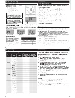
The cooling fan delay setting will
delay the fan from coming on in
cool mode and keep it running
after the compressor shuts off
for a short time to save energy in
some systems.
Cooling Fan
Delay
OFF
You can set the cooling fan
delay to OFF, 15, 30, 60 or 90
seconds. If 15, 30, 60, or 90 is
selected the fan will not turn
on for that many seconds
when there is a call for cool
and will run for that many
seconds after satisfying a call
for cool.
COOL
FAN
DELAY
For Dual Fuel applications (Gas/
Fossil fuel Auxiliary Heat), turn
this setting
ON
to
LOCKOUT
the
Heat Pump (Y) when Auxiliary
Heat (W2) is on. If desired - This
can also be used with Electric
Auxiliary.
You can configure the system
switch for the particular appli-
cation.
Heat - Off - Cool, Heat - Off, Cool -
Off, Heat - Off - Cool - Auto
Note: EM. Heat will show if in
heat pump mode.
System Set
Use the or key until
the desired application is
flashing.
AUTO - Auto Changeover
Dual Fuel
Auxiliary for
Heat
Pump
Will only appear
if Heat pump
setting is turned
ON.
OFF
Will allow Y(1st stage of
Heat) and W2 (Aux Heat) to
run together if called for.
ON
Will de-energize Y termi-
nal 45 seconds after a call for
Auxiliary Heat (W2).
Heat Pump
When turned on the thermostat
will operate a heat pump.
1. EM. Heat will show as an option
in the system switch.
2. Y will be first stage of heat
& cool, W/E will be emergency
heat relay & W2 will be auxiliary
heat relay.
OFF configures the thermostat
for non heat pump systems.
ON configures the thermostat
for heat pump systems.
OFF
HEAT
OFF
COOL
OFF
OFF
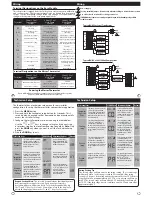
Tech Setup Steps
Adjustment Options
Default
LCD Will Show
SYSTEM
SET
Select GAS for systems that
control the fan during a call for
heat.
Select ELEC to have the
thermostat control the fan during
a call for heat. Will not appear if
Heat Pump is “ON”.
Fan
Operation
GAS
or
ELEC
GAS
GAS
OFF
OFF
This step connects the indoor
sensor with the master
thermostat. The previous step
remote sensor must be set to
YES in order to connect an indoor
sensor.
Finding
Sensor
When NO is selected the
thermostat is unable to
connect to an indoor remote
sensor. When YES is selected
the thermostat is able to
connect to up to four indoor
remote sensors. Go to the
next step FINDING SENSOR to
connect remote sensors.
NO
Remote
Sensor
Enables the use of up to four
indoor sensors.
Selecting YES requires the master
thermostat to be powered with
24V on C and R terminals.
The number shown
represents the zone.
Use or to select the
zone you wish to connect.
The zone setting on the
master and the indoor
sensors must be the same to
connect. See indoor sensors
user guide for detailed
connection information.
See note below for more
information.
1
1
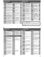
Tech Setup Steps
Adjustment Options
Default
LCD Will Show
Technician Setup
Enables the use of an outdoor
sensor. Connecting an outdoor
sensor allows for a balance point
setting. Selecting YES requires the
master thermostat to be powered
with 24V on C and R terminals.
See the outdoor sensor guide for
more information.
Outdoor
Sensor
When NO is selected the
thermostat is unable to
connect to an outdoor
remote sensor. When YES
is selected the thermostat
is able to connect to an
outdoor remote sensor. Press
and hold connect button
on outdoor sensor until the
master thermostat says
FOUND OUTDOOR on display.
NO
Reminders
Once a reminder has been turned on and set, the elapsed time can be
checked by navigating to its tech setup step. The elapsed time will then
appear in the text field. It can also be reset at that time by holding down
the set
CLEAN
button for 3 seconds. Resetting an expired
reminder can be done without entering tech setup, by holding down
the set
CLEAN
button for 3 seconds from the home screen.
Technician Setup
OUTDOOR
SENSOR
REMOTE
SENSOR
FINDING
SENSOR
Disable the sensor on the master.
At least one indoor remote sensor
must be connected to disable the
local sensor.
Local Temp
Sensor
YES enables local sensor.
NO disables local sensor.
YES
YES
LOCAL
TEMP
SENSOR
Turns on the heat for 10 minutes
each hour if unable to communi-
cate with the master thermostat
if there has been a call for heat in
the last 24 hours.
Freeze
Protection
YES enables freeze protection.
NO disables freeze protection.
YES
FREEZE
PROTECTION
Option for how DHM terminal
energizes.
Note: Set as option 1 if DEHUM
with AC is set to YES.
DHM
Terminal
Use the or key to
select the one of the four
options.
View the DEHUM terminal
chart below for an
explanation of these options.
1
3
dHM
TERMINAL
Tech Setup Steps
Adjustment Options
Default
LCD Will Show
You can configure the D Terminal
as normally-open or normally
closed.
NO= Normally Open
NC= Normally Closed
See Note Below
Dehumidify
Relay
Use the or key to
select NO or NC.
If NO is selected, D will
energize to dehumidify. If
NC is selected, D will be
normally energized. D will
de-energize to dehumidify.
NO
dEHUMIDIFY
dELAY
This feature allows the ther-
mostat to keep multiple stages
of heat or cool energized until
setpoint is satisfied.
Satisfy
Setpoint
Use the or key to
turn on or off.
OFF
SS STAGING
This feature allows a delay to
occur when a second and third
stage is needed. This allows the
previous stage extra time to
satisfy setpoint.
Staging
Delay
Use the or key to se-
lect the number of minutes
to delay each stage.
OFF 5, 10, 15, 30, 45, 60, 90
delay minutes.
OFF
STAGING
DELAY
OFF
HUM Terminal
DHM Terminal
OPTIONS
1
2
3
4
HUM terminal energizes when the ambient
humidity is...
Below the humidity setpoint and heat or
fan is energized.
Below the humidity setpoint and heat is
energized.
Below the humidity setpoint. It will also
energize the fan during a call for humidity.
Below the humidity setpoint.
OPTIONS
1
2
3
4
DUM terminal energizes when the ambient
humidity is...
Above the humidity setpoint and cool or fan
is energized.
Above the humidity setpoint. It will also
energize the fan during a call for dehumidity.
Above the humidity setpoint.
Above the humidity setpoint and the
compressor is not running.
Note:
When the dehumidify terminal is configured as normally-closed,
the base module D terminal LED indicator will be lit when the relay is
closed. When the thermostat calls for dehumidification, the D terminal
LED indicator will turn off.
Note:
Up to four indoor temperature sensors can be connected to one
thermostat. This allows for 5 sensing points (zones). For example: the
local (thermostat) plus four indoor sensors enables 5 sensing points.
To connect an indoor sensor to a thermostat, select 1 on the FINDING
SENSOR technician setup step. Then hold down the light button on the
indoor sensor until it beeps, while in ZONE technician setup step on the
indoor sensor. To connect a second indoor sensor change the
thermostat to read 2 and change the indoor sensor to zone 2. The zone
setting must match between the thermostat and the indoor sensor to
connect. When the connection is established the thermostat will show
FOUND + NAME of the indoor sensor in the system information area of
display.
Balance Point:
The system operates differently when a balance point is used. On a dual
fuel system, the balance point outdoor temperature setting will be the
outdoor temperature at which the thermostat chooses either the heat
pump or gas furnace. For example: A balance point setting of 30°F will
turn on only the heat pump above 30°F and only the gas furnace below
30°F. Y1 will be stage one above 30°F and W2 will be stage one below
30°F. A heat pump with electric auciliary will energize the heat pump
above and below balance point. The electric auxiliary will only energize
below balance point. For Example: A balance point setting of 40°F, will
turn on the heat pump above 40°F and turn on the heat pump and
electric auxiliary below 40°F.
A6
OFF


